Mazda CX-5 Service & Repair Manual: Refrigerant Charging
CAUTION:
-
Do not use a different type of refrigerant or charge beyond the specified level. Otherwise, cooling ability will be lowered and the A/C compressor could be damaged.
Charging Recycled HFC-134a Refrigerant
1. Connect an HFC-134a recovery/recycling/recharging device to the vehicle and follow the device manufacturer’s instructions.
Charging Preparation
1. Install the manifold gauge set.
2. Connect the tap pin side of the charging hose to the air purge valve of the manifold gauge.
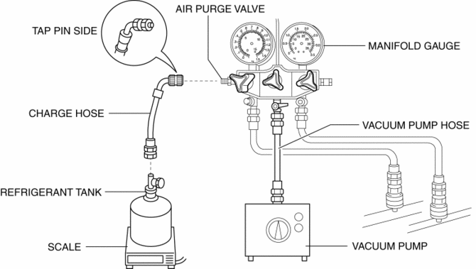
3. Connect the vacuum pump hose to the center joint of the manifold gauge.
4. Connect the vacuum pump hose to the vacuum pump.
5. Connect the charging hose to the refrigerant tank.
6. Place the refrigerant tank on the scale.
-
Regular amount of refrigerant (approx. quantity)
-
465—515
g {16.5—18.1
oz}
Evacuation
1. Open all the valves of the manifold gauge.
CAUTION:
-
Close the manifold gauge valve immediately after stopping the vacuum pump. If the valve is left open, the vacuum pump oil will back flow into the refrigeration cycle and cause a decrease in the efficiency of the air conditioner.
2. Start the vacuum pump and let it operate for 15 min
.
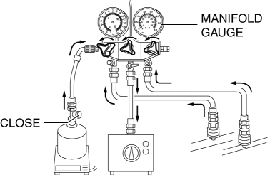
3. Verify that high? and low-pressure side readings of the manifold gauge are at –101 kPa {–1.03 kgf/cm2, –14.6 psi}
. Close each valve of the manifold gauge.
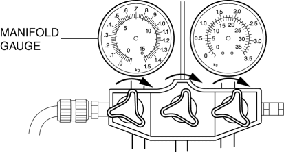
Airtightness Check
1. Stop the vacuum pump and wait for 5 min
.
2. Check the high? and low-pressure side readings of the manifold gauge.
-
If the reading has changed, inspect for leakage and go to Evacuation..
-
If the reading has not changed, go to Charging New R-134a Refrigerant..
Charging New HFC-134a Refrigerant
1. Open the valve of the refrigerant tank.
2. Weigh the refrigerant tank to charge the suitable amount of refrigerant.
WARNING:
-
If the refrigerant system is charged with a large amount of refrigerant when inspecting for gas leakage, and if any leakage should occur, the refrigerant will be released into the atmosphere. In order to prevent the accidental release of refrigerant which can destroy the ozone layer in the stratosphere, follow the proper procedures and charge with only a small amount of refrigerant when inspecting for gas leakage.
-
If charging the system with refrigerant using service cans, running the engine with the high-pressure side valve open is dangerous. Pressure within the service cans will increase and the cans could explode, scattering metal fragments and liquid refrigerant that can seriously injure you. Therefore, do not open the high-pressure side valve while the engine is running.
3. Open the low-pressure side valve of the manifold gauge.
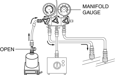
4. When the high-pressure side reading increases to 0.098 MPa {1.0 kgf/cm2, 14 psi}
, close the low-pressure side valve of the manifold gauge.
5. Inspect for leakage from the cooler pipe/hose connections using the gas leak tester.
-
If there is no leakage, go to Step 7.
-
If leakage is found at a loose joint, tighten the joint, then go to next step.
6. Inspect for leakage again.
-
If there is no leakage after tightening the joint, go to next step.
-
If there is still a leakage at the same joint, discharge the refrigerant and then repair the joint. Repeat the charging procedure from evacuation.
WARNING:
-
If charging the system with refrigerant using service cans, running the engine with the high-pressure side valve open is dangerous. Pressure within the service cans will increase and the cans could explode, scattering metal fragments and liquid refrigerant that can seriously injure you. Therefore, do not open the high-pressure side valve while the engine is running.
7. Open the low-pressure side valve of the manifold gauge and charge with refrigerant until the weight of refrigerant tank has decreased 250 g {8.82 oz}
from the amount in Step 2.
8. Close the low-pressure side valve of the manifold gauge.
WARNING:
-
If charging the system with refrigerant using service cans, running the engine with the high-pressure side valve open is dangerous. Pressure within the service cans will increase and the cans could explode, scattering metal fragments and liquid refrigerant that can seriously injure you. Therefore, do not open the high-pressure side valve while the engine is running.
9. Start the engine and actuate the A/C compressor.
10. Open the low-pressure side valve of the manifold gauge and charge with refrigerant until the weight of the refrigerant tank has decreased regular amount from the amount in Step 2.
11. Close the low-pressure side valve of the manifold gauge and the valve of the refrigerant tank.
12. Stop the engine and A/C compressor.
Leak Test
1. Inspect for leakage using the gas leak tester.
-
If there is no leakage, go to Step 3.
-
If leakage is found at a loose joint, tighten the joint, then go to the next step.
2. Inspect for leakage again.
-
If there is no leakage after tightening the joint, go to the next step.
-
If there is still leakage at the same joint, discharge the refrigerant and then repair the joint. Repeat the charging procedure from evacuation.
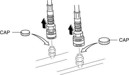
3. Disconnect the quick couplers from the charging valves.
4. Install the caps to the charging valves.
 Generator [Skyactiv G 2.0]
Purpose, Function
The generator operates by obtaining drive force from the engine via the drive
belt and generates the required electricity for electronic devices.
Construction
...
 Starter Cut Off Control [Skyactiv G 2.0]
Outline
The PCM controls energization to the starter relay according to an immobilizer
system request to improve security.
While not in P or N position, the starter relay energizatio ...
Other materials:
Washer Motor Inspection
1. Disconnect the negative battery cable..
2. Set the front over fender aside..
3. Set the mudguard (RH) aside..
4. Remove the front bumper..
5. Disconnect the washer motor connector from the washer motor.
6. Disconnect the windshield washer hose from the washer motor.
7. Disconnect the ...
Traction Control System (TCS)
The Traction Control System (TCS) enhances traction and safety by controlling
engine torque and braking.
When the TCS detects driving wheel slippage, it lowers engine torque and operates
the brakes to prevent loss of traction.
This means that on a slick surface, the engine adjusts automaticall ...
Differential Oil Temperature Sensor Removal/Installation
WARNING:
Hot differential oil may cause severe burns. Do not perform maintenance while
differential oil is hot.
1. Disconnect the negative battery cable.
2. Disconnect the differential oil temperature sensor connector.
3. Remove the differential oil temperature sensor.
4. ...
