
Mazda CX-5 Service & Repair Manual: Magnet Clutch [Manual Air Conditioner]
Purpose
-
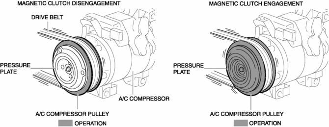
The magnetic clutch transmits the rotation force from the engine to the shaft in the A/C compressor.
Function
-
The magnetic clutch engages or disengages the magnetic clutch and the A/C turns on or off by switching the power transmission from the engine.
Construction
-
The magnetic clutch is installed to the A/C compressor.
-
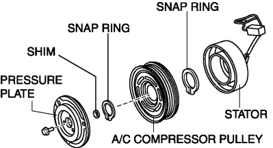
The magnetic clutch consists of the following parts:
-
Pressure plate
-
A/C compressor pulley
-
Stator
-
Snap ring
-
Shim
Operation
Magnetic clutch disengagement
1. If there is no energization in the magnetic clutch stator from the A/C relay, the pressure plate cannot be engaged with the A/C compressor pulley because the magnetic clutch stator does not operate.
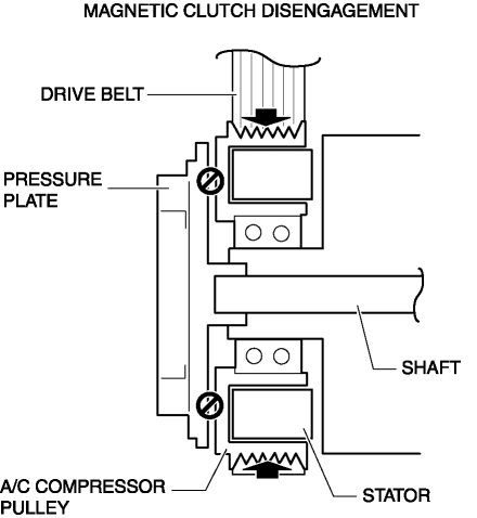
2. The rotation force from the drive belt is only transmitted to the A/C compressor pulley and the pulley spins.
Magnetic clutch engagement
1. If there is energization in the magnetic clutch stator from the A/C relay, the magnetic clutch stator operates and the pressure plate is engaged with the A/C compressor pulley.
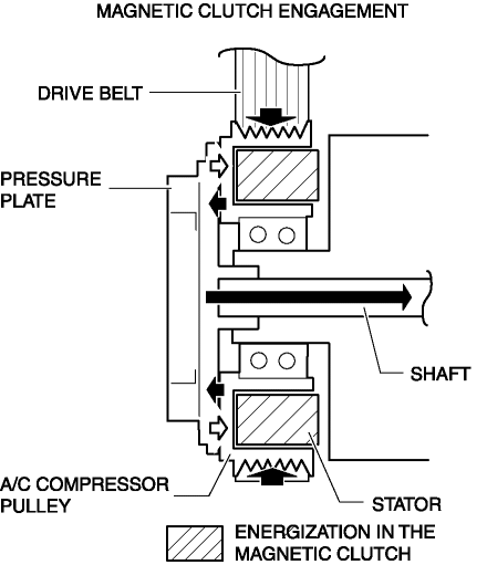
2. The rotation force from the drive belt is transmitted to the compressor shaft through the pressure plate from the A/C compressor pulley.
Fail-safe
-
Function not equipped.
 Magnet Clutch [Full Auto Air Conditioner]
Purpose
The magnetic clutch transmits the rotation force from the engine to the shaft
in the A/C compressor.
Function
The magnetic clutch engages or disengages the magnetic clut ...
 Magnetic Clutch Adjustment [Full Auto Air Conditioner]
1. Measure the clearance around the entire circumference between the pressure
plate and A/C compressor pulley using a thickness gauge.
2. Verify the clearance.
If not within the specif ...
Other materials:
Valve, Valve Spring, Valve Seal, Valve Guide
Purpose, Function
Valve
The intake valve is pressed down by the cam, the intake air passage is opened,
and air is introduced into the cylinder.
The exhaust valve is pressed down by the cam, the exhaust air passage is
opened, and combustion gas is exhausted from the cylinder.
...
Awd Control Module Configuration
CAUTION:
When performing configuration, it is necessary to read the coupling component
calibration data from the AWD control module before replacing it. Connect the
M-MDS to the vehicle and perform vehicle identification before removing the
AWD control module. The coupling component ...
Camshaft Position (CMP) Sensor Inspection
Intake CMP Sensor
Visual inspection
CAUTION:
When replacing the CMP sensor, make sure there is no foreign material on
it such as metal shavings. If it is installed with foreign material, the sensor
output signal will malfunction resulting from fluctuation in magnetic flux and
caus ...
