Mazda CX-5 Service & Repair Manual: Rear Stabilizer Control Link Inspection
1. Remove the rear stabilizer control link..
2. Inspect for bending or damage. If there is any malfunction, replace the rear stabilizer control link.
3. Rotate the ball joint stud 10 times
and shake it side to side 10 times
.
4. Measure the ball-joint rotational torque using an Allen wrench and a torque wrench.
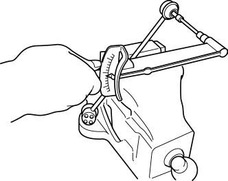
-
Rear stabilizer control link ball joint starting torque
-
0.8—3.5 N·m {8.2—35 kgf·cm, 7.1—30 in·lbf}
-
If not within the specification, replace the rear stabilizer control link.
-
Even when within the specification, if there is excessive play in the ball joint, replace the rear stabilizer control link.
 Rear Shock Absorber Removal/Installation
1. Remove in the order indicated in the table.
2. Install in the reverse order of removal.
1
Rear shock absorber upper nut
(See Rear Shock Absorber Upper nut Install ...
 Rear Stabilizer Removal/Installation [2 Wd]
WARNING:
Verify that the rear crossmember is securely supported by a jack. If the
rear crossmember falls off, it can cause serious injury or death, and damage
to the vehicle.
C ...
Other materials:
Passenger Side Air Bag Module [Standard Deployment Control System]
Purpose
When the passenger-side air bag module receives an impact from a frontal
or frontal offset collision, the operation (deployment) of the air bag mediates
the impact to the head and face of the front passenger.
Function
When the passenger-side air bag module receives ...
Rear Seat Back Frame Removal/Installation
CAUTION:
When performing the procedure with a rear seat removed from the vehicle,
perform the procedure on a clean cloth so as not to damage or soil the seat.
6:4 Split Type
1. Remove the trunk board..
2. Remove the rear seat back..
3. Remove the headrest.
4. Open fasteners A ...
Mass Air Flow (MAF) Sensor Inspection
Visual Inspection
1. Remove the MAF sensor/IAT sensor No.1..
2. Visually inspect the MAF sensor for the following:
Damage, cracks, soiling
Rusted sensor terminal
Bent sensor terminal
If there is any malfunction, repair or replace the MAF sensor/IAT sensor
...
