
Mazda CX-5 Service & Repair Manual: Front Seat Adjuster Unit Removal/Installation
WARNING:
-
Handling a side air bag improperly can accidentally operate (deploy) the air bag, which may seriously injure you. Read the service warnings/cautions in the Workshop Manual before handling the front seat (side air bag integrated)..
-
If the sliding mechanisms on both sides are not locked after assembling the front seat, the front seat will operate accidentally while the vehicle is driven, which could result in serious injury. After assembling the front seat, shake it up and down and verify that the sliding mechanism on the both sides are locked.
CAUTION:
-
If the slide bar is operated after the front seat is removed, the left/right slide positions will deviate and the adjuster unit could be damaged after the front seat is installed. After removing a front seat, do not operate the slider lever.
-
Verify that there are no malfunctions in the forward/back slide of the seat and in the adjuster unit after installing a front seat.
-
When performing the procedure with a front seat removed from the vehicle, perform the procedure on a clean cloth so as not to damage or soil the seat.
-
When the passenger's seat is removed, perform the seat weight sensor inspection using the M-MDS after installing the passenger's seat..
-
When the passenger's seat is replaced with a new one, perform the seat weight sensor calibration using the M-MDS..
Driver-side (with power seat system)
1. Switch the ignition off (LOCK).
2. Disconnect the negative battery cable and wait for 1 min
..
3. Remove the following parts:
a. Front seat.
b. Front seat side cover.
c. Front buckle.
d. Seat track position sensor.
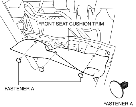
4. Remove fasteners A and set the front seat cushion trim aside.
5. Using a flathead screwdriver, disconnect the connector in the direction of the arrow (2) while releasing tab B in the direction of the arrow (1) shown in the figure.
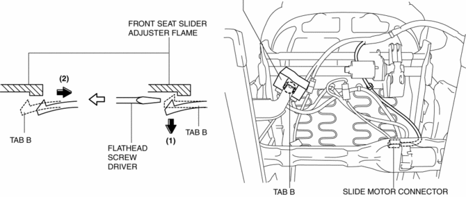
6. Disconnect the slide motor connector.
7. Remove bolts A.
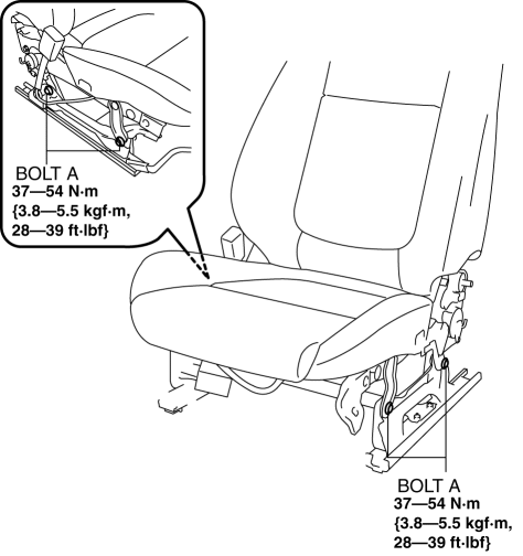
8. Remove the front seat adjuster unit.
9. Install in the reverse order of removal.
Driver-side (without power seat system)
1. Switch the ignition off (LOCK).
2. Disconnect the negative battery cable and wait for 1 min
..
3. Remove the following parts:
a. Front seat.
b. Front seat side cover.
c. Front buckle.
d. Seat track position sensor.
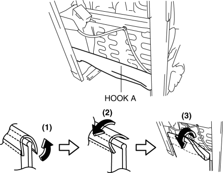
4. Slide hook A in the order of arrows (1), (2), (3) shown in the figure and set the front seat cushion trim aside.
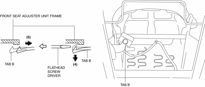
5. Using a flathead screwdriver, disconnect the connector in the direction of the arrow (5) while releasing tab B in the direction of the arrow (4) shown in the figure.
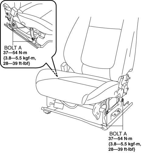
6. Remove bolts A.
7. Install in the reverse order of removal.
Passenger-side
1. Switch the ignition off (LOCK).
2. Disconnect the negative battery cable and wait for 1 min
..
3. Remove the following parts:
a. Front seat.
b. Front seat side cover.
c. Front buckle.
d. Seat weight sensor control module.
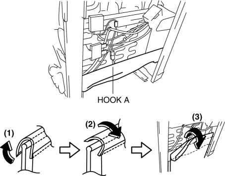
4. Slide hook A in the order of arrows (1), (2), (3) shown in the figure and set the front seat cushion trim aside.
5. Disconnect the seat weight sensor control module connector.
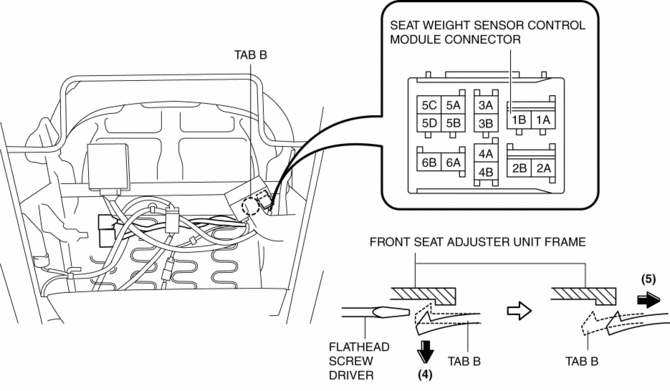
6. Using a flathead screwdriver, disconnect the connector in the direction of the arrow (5) while releasing tab B in the direction of the arrow (4) shown in the figure.
7. Remove bolts A.
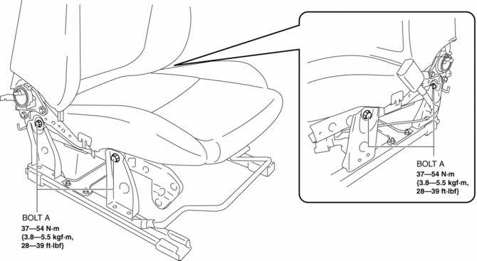
8. Install in the reverse order of removal.
 Front Seat
Purpose, Function
The front seats are structured to reduce impact force applied to the head
of the occupant in a vehicle collision.
8WAY or 6WAY power seats have been adopted on the ...
 Front Seat Back Component Removal/Installation
WARNING:
Handling a side air bag improperly can accidentally operate (deploy) the
air bag, which may seriously injure you. Read the service warnings/cautions
in the Workshop Manual befor ...
Other materials:
Cruise Set Indicator Light (Green)
Purpose/Function
Illuminates during the cruise control system operation to inform the driver
that the cruise control system is operating.
Construction
Built into the instrument cluster.
Operation
Illuminates during the cruise control system operation.
...
Side Step Molding Removal/Installation
1. Set the rear over fender aside..
2. Insert a tape-wrapped flathead screwdriver shown in the figure and remove
the clip A in the direction of arrow (1).
3. Slide the side step molding in the direction of the arrow (2) shown in the
figure and remove clips B from side step molding.
4. ...
Rear Drive Shaft
Purpose, Function
Engine noise and vibration have been reduced due to adoption of a bell joint
on the wheel side of the constant velocity joint.
A low noise and vibration double offset joint with low slide resistance has
been adopted for the differential side of the constant vel ...
