Mazda CX-5 Service & Repair Manual: Rear Brake (Disc) Inspection
Brake Judder Repair Hints
Description
1. Brake judder concern has the following 3 characteristics:
Steering wheel vibration
1. The steering wheel vibrates in the rotation direction. This characteristic is most noticeable when applying brakes at a vehicle speed of 100—140 km/h {62.2—86.9 mph}
.
Floor vibration
1. When applying the brakes, the vehicle body shakes back and forth. The seriousness of the shaking is not influenced by vehicle speed.
Brake pedal vibration
1. When applying the brakes, a pulsating force tries to push the brake pad back. The pulsation is transmitted to the brake pedal.
2. The following are the main possible causes of brake judder:
Due to an excessive runout (side-to-side wobble) of the disc plate, the thickness of the disc plate is uneven.
1. If the runout is more than 0.05 mm {0.002 in}
at the position 10 mm {0.39 in}
from the disc plate edge, uneven wear occurs on the disc plate because the pad contacts the plate unevenly.
2. If the runout is less than 0.05 mm {0.002 in}
, uneven wear does not occur.
The disc plate is deformed by heat.
1. Repeated panic braking may raise the temperature in some portions of the disc plate by approx. 1,000 °C {1,832 °F}
. This results in a deformed disc plate.
Due to corrosion, the thickness and friction coefficient of the disc plate change.
1. If the vehicle is parked in damp conditions for a long time, corrosion occurs on the friction surface of the disc plate.
2. The thickness of corrosion is uneven and sometimes appears like a wave pattern, which changes the friction coefficient and causes a reaction force.
Inspection and repair procedure
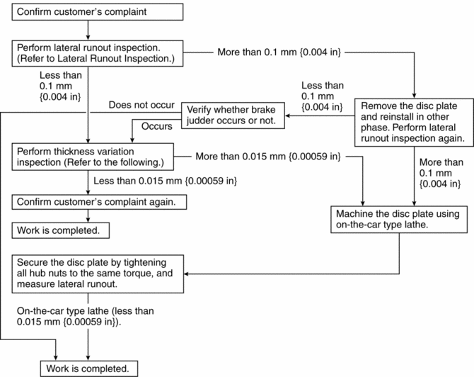
Lateral runout inspection
1. To secure the disc plate and the hub, insert the washer (thickness 10 mm {0.39 in}
, inner diameter more than 12 mm {0.47 in}
) between each hub bolt and the hub nut, then tighten all the hub nuts.
NOTE:
-
The component parts of the SST
(49 B017 001 or 49 G019 003) can be used as a suitable washer.
2. After tightening all the hub nuts to the same torque, put the dial gauge on the friction surface of the disc plate 10 mm {0.39 in}
from the disc plate edge.
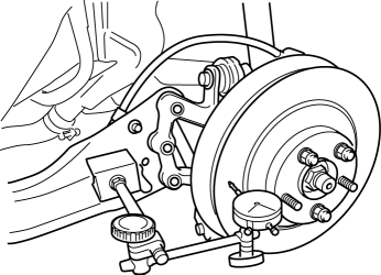
3. Rotate the disc plate one time and measure the runout.
-
Rear disc plate runout limit
-
0.1 mm {0.004 in}
Thickness variation inspection
1. Clean the disc plate-to-pad friction surface using a brake cleaner.
2. Measure the points indicated in the illustration using a caliper (micrometer).
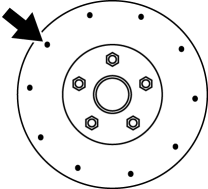
3. Subtract the minimum value from the maximum, and if the result is not within the specification, machine the disc plate using a lathe.
-
Thickness variation limit
-
0.015 mm {0.00059 in}
WARNING:
-
Do not exceed minimum disc plate thickness.
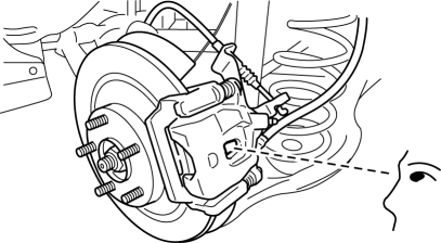
Disc Plate Thickness Inspection
CAUTION:
-
Excessive runout may result if the disc plate is removed from the vehicle then machined. Machine the disc plate while installed on the vehicle.
1. Measure the thickness of the disc plate.
-
If the thickness is not within the specification, replace the disc plate.
-
Minimum rear disc plate thickness
-
8.0 mm {0.31 in}
-
Minimum rear disc plate thickness after machining using a brake lathe on-vehicle
-
8.8 mm {0.35 in}
Disc Pad Thickness Inspection
1. Jack up the front of the vehicle and support it with safety stands.
2. Remove the wheels and tires.
3. Verify the remaining thickness of the pads.
-
Minimum rear disc pad thickness
-
2.0 mm {0.079 in} min.
4. Replace the pads as a set (right and left wheels) if either one is at or less than the minimum thickness.
 Rear Brake (Disc)
Purpose/Function
Large diameter, solid-disc type front brakes with a 303 mm {11.9 in} diameter
and 10 mm {0.39 in} thickness have been adopted, improving braking force and
fade resistance ...
 Rear Brake (Disc) Removal/Installation
1. Loosen the adjusting nut..
2. Remove in the order indicated in the table.
3. Install in the reverse order of removal.
4. After installation, add brake fluid, bleed the air, and inspect for fl ...
Other materials:
Shift Solenoid No.2 [Fw6 A EL, Fw6 Ax EL]
Purpose/Function
Shift solenoid No.2 adjusts the hydraulic pressure in the 2-6 brake circuit
based on the current demand from the TCM according to the vehicle conditions.
Construction
Shift solenoid No.2 is installed to the solenoid control valve body.
Shift solenoid N ...
Rear Lower Arm Removal/Installation
WARNING:
Be careful not to allow the coil spring to fly off when removing/installing
the coil spring. Otherwise, the coil spring could fly off and cause serious
injury or death, or damage to the vehicle.
1. When working on the left side of the vehicle, disconnect the auto lev ...
Spare Tire and Tool Storage
Spare tire and tools are stored in the locations illustrated in the diagram.
Except Mexico
Mexico
Jack
To remove the jack
1. Open the trunk board.
2. Secure the trunk board by attaching the hook to the head restraint.
Without luggage compartment cover
With luggage compartment cover
...
