Mazda CX-5 Service & Repair Manual: Fan Switch Inspection [Manual Air Conditioner]
1. Disconnect the negative battery cable..
2. Remove the following parts:
a. Shift lever knob (MTX).
b. Glove compartment.
c. Front console box.
d. Shift panel.
e. Upper panel.
f. Rear console.
g. Side wall.
h. Decoration panel.
i. Front console.
3. Remove the climate control unit..
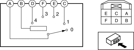
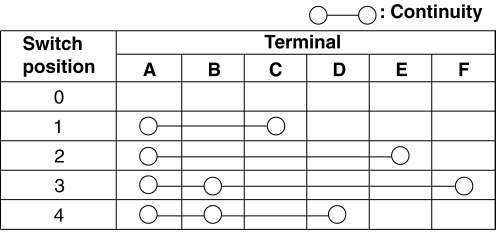
4. Verify that the continuity between the fan switch terminals as indicated in the table.

-
If there is any malfunction, replace the fan switch.

 Engine Coolant Temperature (ECT) Sensor
Purpose/Function
Detects the ECT as basic information for mainly determining the fuel injection
amount.
Detects the ECT and inputs it to the PCM as an ECT signal.
The ECT sen ...
 Fuel Gauge Sender Unit Inspection [2 Wd]
NOTE:
For the fuel gauge sender unit removal/installation, refer to the fuel pump
removal/installation because the fuel gauge sender unit is integrated with the
fuel pump..
1. Veri ...
Other materials:
Fuel Gauge Sender Unit Removal/Installation [Awd]
WARNING:
Always keep sparks and flames away from fuel when servicing the fuel system.
Fuel can be easily ignited which could cause serious injury or death, and damage
to equipment.
Fuel line spills and leakage from the pressurized fuel system are dangerous.
Fuel can ignite a ...
Back Up Light Bulb Removal/Installation
1. Disconnect the negative battery cable..
2. Insert a tape-wrapped flathead screwdriver into the service hole in the position
shown in the figure.
3. Move the flathead screwdriver in the direction of the arrow (1) shown in the
figure, pull out the service hole cover from the liftgate, a ...
Front Seat Adjuster Unit Removal/Installation
WARNING:
Handling a side air bag improperly can accidentally operate (deploy) the
air bag, which may seriously injure you. Read the service warnings/cautions
in the Workshop Manual before handling the front seat (side air bag integrated)..
If the sliding mechanisms on both side ...
