Mazda CX-5 Service & Repair Manual: Rear ABS Wheel Speed Sensor Inspection [Awd]
Installation Visual Inspection
1. Inspect the following items:
-
If there is any malfunction, replace the applicable part.
a. Excessive play of the ABS wheel-speed sensor
b. Deformation of the ABS wheel-speed sensor
c. Deformation or damage of the ABS sensor rotor
Clearance Inspection
1. Remove the ABS wheel-speed sensor.
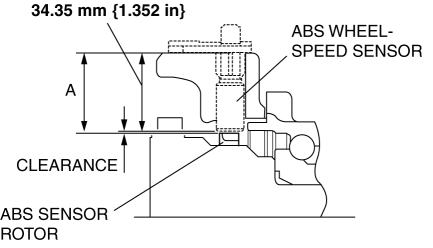
2. Measure the distance between the ABS wheel-speed sensor installation surface and the ABS sensor rotor. This is dimension A.

3. Calculate the clearance between the front ABS wheel-speed sensor and the ABS sensor rotor using the following formula:
-
Clearance (mm {in}) = A-34.35 {1.352}
4. Verify that the clearance between the ABS sensor rotor and the ABS wheel-speed sensor is as indicated below.
-
If there is any malfunction, replace it.
-
Clearance
-
0.3—1.4 mm {0.02—0.05 in}
Sensor Output Value Inspection
1. Switch the ignition to off.
2. Connect the M-MDS to the DLC-2.
3. Select the following PIDs using the M-MDS:
-
WSPD_SEN_LR (LR ABS wheel-speed sensor)
-
WSPD_SEN_RR (RR ABS wheel-speed sensor)
4. Start the engine and drive the vehicle.
5. Verify that the display of the M-MDS shows the same value as the speedometer.
-
If there is any malfunction, replace the ABS wheel-speed sensor.
 Rear ABS Wheel Speed Sensor Inspection [2 Wd]
Installation Visual Inspection
1. Inspect the following items:
If there is any malfunction, replace the applicable part.
a. Excessive play of the ABS wheel-speed sensor
b. Deformation ...
 Rear ABS Wheel Speed Sensor Removal/Installation
1. Remove the trunk board..
2. Remove the trunk end trim..
3. Remove the rear scuff plate..
4. Remove the trunk side trim..
5. Disconnect the rear ABS wheel-speed sensor connector.
6. Pr ...
Other materials:
Power Steering Malfunction Indicator Light
Purpose
The power steering malfunction indicator light warns the driver that there
is a malfunction with the electric power steering (EPS) system.
Function
If there is a malfunction in the EPS system, the power steering malfunction
indicator light illuminates.
If th ...
Hood
WARNING
Always check that the hood is closed and securely locked:
A hood that is not closed and securely locked is dangerous as it could fly open
while the vehicle is moving and block the driver's vision which could result in
a serious accident.
Opening the Hood
1. With the vehicle parke ...
Rear Differential Removal/Installation
WARNING:
When replacing the coupling component, read the special character string
before installing a new coupling component and write it to the AWD control module
after replacement. The special character string is indicated in the two locations
shown in the figure.
1. D ...
