Mazda CX-5 Service & Repair Manual: Hydraulic Pressure Control System Outline [Fw6 A EL, Fw6 Ax EL]
Outline
-
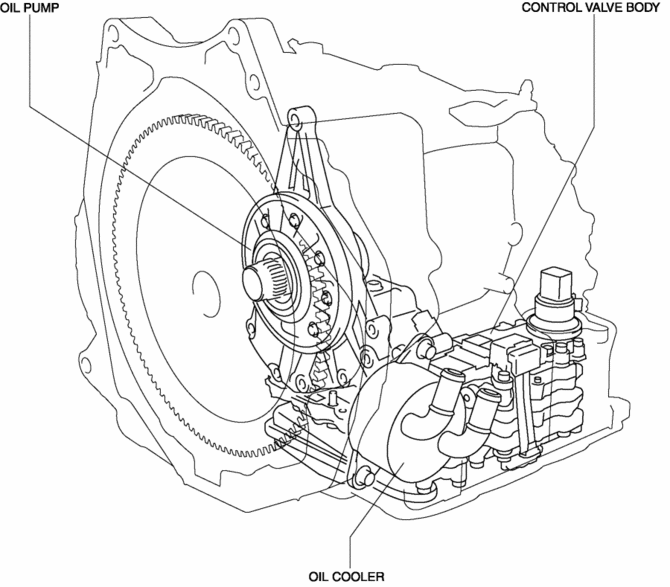
The hydraulic control mechanism consists of an oil cooler which maintains the hydraulic pressure at the optimum temperature, a control valve body and each shift valve which perform adjustment and circuit switching of the hydraulic pressure based on the control content calculated by the TCM, and the oil pump which generates the hydraulic pressure of each clutch and brake.
Construction
Structural view

 Fuel Injection Control System
Outline
Performs optimum fuel injection according to engine operation conditions.
The PCM determines the engine operation conditions based on the signals from
each input device and d ...
 Hydraulic Variable Valve Timing Control
Outline
Changes the exhaust valve timing according to engine operation conditions
to improve engine output, fuel economy, and emission performance.
Based on each input signal, the PC ...
Other materials:
Clutch Pedal Position (CPP) Switch Inspection [Skyactiv G 2.0]
Continuity Inspection
1. Verify that the CPP switch is installed properly..
2. Disconnect the negative battery cable..
3. Disconnect the CPP switch connector.
4. Verify that the continuity between CPP switch terminals A and B when the clutch
pedal is depressed and when it is released is acc ...
Rear Seat Back Striker Removal/Installation
1. Disconnect the negative battery cable..
2. Press the push knob to fold the rear seat back.
3. Remove the following parts:
a. Trunk board.
b. Trunk end trim.
c. Rear scuff plate.
d. Trunk side trim.
4. Remove the bolts.
5. Remove the rear seat back striker.
6. Install in the ...
SRS Air Bag Deployment Criteria
This chart indicates the applicable SRS equipment that will deploy depending
on the type of collision.
(The illustrations are the representative cases of collisions.)
X: The SRS air bag equipment is designed to deploy in a collision.
*1 (With Driver and Front Passenger Occupant Classification ...
