Mazda CX-5 Service & Repair Manual: Clock Spring Inspection [Two Step Deployment Control System]
1. Disconnect the negative battery cable and wait for 1 min or more
..
2. Remove the driver?side air bag module..
3. Remove the steering wheel..
4. Remove the column cover..
5. Remove the clock spring..
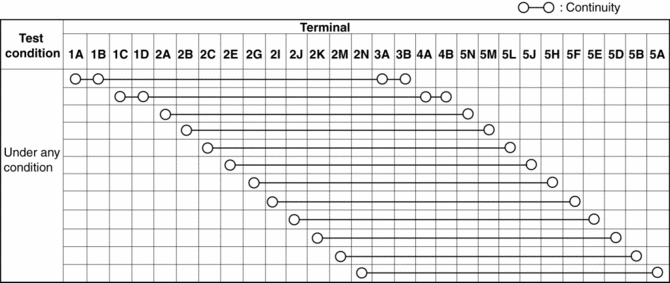
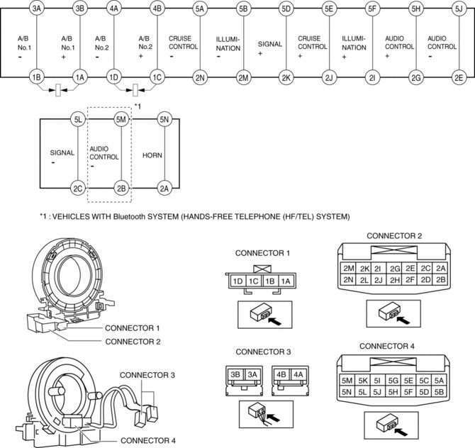
6. Verify that the continuity is as indicated in the table.
-
If not as indicated in the table, replace the clock spring.
NOTE:
-
When the vehicle-side connector for the clock spring is disconnected, terminals 1A, 1B, 1C and 1D are shorted to prevent unexpected operation (deployment) of the air bag module.
 Clock Spring Inspection [Standard Deployment Control System]
1. Disconnect the negative battery cable and wait for 1 min or more..
2. Remove the driver?side air bag module..
3. Remove the steering wheel..
4. Remove the column cover..
5. Remove the cloc ...
 Clock Spring Removal/Installation [Standard Deployment Control System]
CAUTION:
If the disc on the combination switch is deformed or has foreign material
adhering to it, performance of the steering angle sensor may be reduced, causing
abnormal operation. Wh ...
Other materials:
Location of the Tire Label (Placard)
You will find the tire label containing tire inflation pressure by tire size
and other important information on the driver's side B-pillar or on the edge of
the driver's door frame.
SAMPLE
Recommended Tire Inflation Pressure
On the tire label you will find the recommended tire infla ...
Main Relay Control [Skyactiv G 2.0]
Outline
Supplies power to each part by switching the main relay on/off at the optimal
timing according to the vehicle conditions.
Block Diagram
Operation
When the ignition is switched ON, the main relay turns on and electrical
power is supplied to each sensor and devic ...
Expansion Valve
Purpose
The expansion valve atomizes liquid refrigerant to facilitate cooling of
the evaporator.
Function
The expansion valve reduces the pressure of liquid refrigerant rapidly to
facilitate vaporization of the atomized refrigerant at the evaporator, and adjusts
the refr ...
