
Mazda CX-5 Service & Repair Manual: Variable Valve Timing Mechanism
Outline
-
Achieves optimum valve timing according to the driving conditions by the variable valve timing mechanism changing the phases of the camshaft.
-
An electric type variable valve timing mechanism on the intake side and a hydraulic pressure type on the exhaust side has been adopted. The expansion of the valve opening angle and the accuracy of the intake and exhaust controls have been improved.
-
The electric variable valve timing mechanism obtains higher response than the hydraulic variable valve timing mechanism. As a result, expansion of overlap and the closing timing of the intake valve are achieved.
Structural View
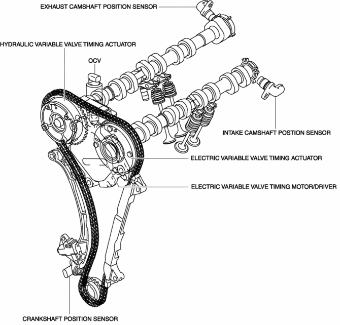
Structure
|
Part name |
Function |
|
Hydraulic variable valve timing actuator |
The hydraulic variable valve timing actuator operates according to the hydraulic pressure and changes the phases of the exhaust camshaft. |
|
Electric variable valve timing actuator |
The electric variable valve timing actuator changes the phases of the intake camshaft. |
|
Electric variable valve timing motor/driver |
Operates the electric variable valve timing actuator based on the signals from the PCM. |
|
OCV |
Operated by current (duty signal) from the PCM. Controls the hydraulic oil passages to the hydraulic variable valve timing actuator. |
|
Intake camshaft position sensor |
Sends the intake camshaft position signal to the PCM. |
|
Exhaust camshaft position sensor |
Sends the exhaust camshaft position signal to the PCM. |
|
Crankshaft position sensor |
Sends the crankshaft position signal to the PCM. |
Operation
At engine start
-
Engine startability has been improved by utilizing the features of the operable electric VVT even under the engine stop condition and controlling the optimal timing according to engine conditions.
Light/medium load range
-
Pumping loss* is reduced by properly controlling the timing of intake and exhaust, improving the fuel consumption rate.
High load range
-
By properly controlling the timing of the intake and exhaust and using the effect of scavenging residual gas in the cylinder and the inertia charging effect, the volumetric efficiency and the output are improved.
 Valve Mechanism
Outline
A DOHC type valve system has been adopted and consists of four valves (two
intake valves and two exhaust valves) per cylinder for a total of 16 valves
operated by two camshafts.
...

Other materials:
Front Console Box Removal/Installation
NOTE:
Affix protective tape to the position shown in the figure.
1. Insert a tape-wrapped flathead screwdriver in the position indicated by the
arrow in the figure and detach clips A.
2. Pull the front console box in the direction of the arrow (2) and remove it
while d ...
Fan Switch Inspection [Manual Air Conditioner]
1. Disconnect the negative battery cable..
2. Remove the following parts:
a. Shift lever knob (MTX).
b. Glove compartment.
c. Front console box.
d. Shift panel.
e. Upper panel.
f. Rear console.
g. Side wall.
h. Decoration panel.
i. Front console.
3. Remove the climate control u ...
Front Stabilizer Control Link Inspection
1. Remove the front stabilizer control link..
2. Inspect for bending or damage. If there is any malfunction, replace the front
stabilizer control link.
3. Rotate the front stabilizer control link ball joint stud 10 times and
shake it side to side 10 times.
4. Measure the front stabilizer c ...
