Mazda CX-5 Service & Repair Manual: Tcs Control
Outline
-
The TCS control actuates torque reduction through engine control, as well as using brake control to control traction.
NOTE:
-
Engine control: Engine output is lowered by fuel cut and ignition timing control to reduce the traction, preventing driving wheel slip.
-
Brake control: Brake fluid pressure from the hydraulic unit (HU) to the driving wheel that is slipping is increased, operating the brake and preventing driving wheel slip.
Features
-
The left and right wheels are controlled at the same time by engine control. Therefore, when the road surface friction coefficients differ between the left and right wheels, proper torque reduction cannot be performed separately for each wheel. When this occurs, torque reduction is performed by independent left and right wheel brake control, providing more stable vehicle control.
-
The TCS OFF switch allows the driver to optionally enable/disable the TCS control at the driver's discretion.
-
When both driving wheels are stuck, traction control according to the driver's operation can be performed by inhibiting the TCS control.
-
The TCS control returns to normal operation automatically at the next ignition cycle.
Construction
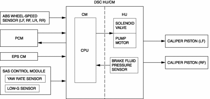
Block Diagram
Operation
-
TCS control detects driving wheel spin based on the signals listed below, sends torque reduction request signals to the PCM, and also controls the solenoid valves and pump motor in the DSC HU/CM.
-
Vehicle wheel speed signals from the font and rear ABS wheel-speed sensors
-
Engine torque signal from the PCM
-
Steering angle signal from the EPS CM
-
Yaw rate and lateral-G signals from the SAS control module
-
Fluid pressure signal from the brake fluid pressure sensor (built into the DSC HU/CM)
 Precaution [Dynamic Stability Control (DSC)]
1. The ABS warning light and/or brake system warning light and/or TCS/DSC indicator
light and/or TCS OFF indicator light illuminate even when the system is normal.
Warning ...
 Tcs Off Switch Inspection
1. Remove the TCS OFF switch..
2. Verify that the resistance between the TCS OFF switch terminals B and C is
as indicated in the table.
If not as indicated in the table, replace the TCS OF ...
Other materials:
Engine Coolant Level Inspection
WARNING:
Never remove the cooling system cap or loosen the radiator drain plug while
the engine is running, or when the engine and radiator are hot. Scalding engine
coolant and steam may shoot out and cause serious injury. It may also damage
the engine and cooling system.
Tu ...
Outside the United States/Canada
Government regulations in the United States/Canada require that automobiles meet
specific emission regulations and safety standards. Therefore, vehicles built for
use in the United States/Canada may differ from those sold in other countries.
The differences may make it difficult or even impossi ...
When Warning/Indicator Lights Illuminate/Flash
If the brake system warning light illuminates
If the light stays on after the parking brake is fully released there may be
a problem with the brakes.
Drive to the side of the road and park off the right-of-way.
You may notice that the pedal is harder to depress or that it may go closer to
t ...
