Mazda CX-5 Service & Repair Manual: Synchronizer Mechanism [C66 M R]
Purpose, Function
-
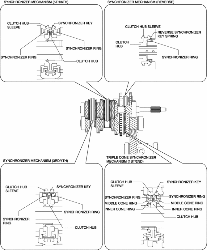
For smooth gear changes, the synchronizer mechanism synchronizes the rotation of the engaging area and engages gears.
Construction
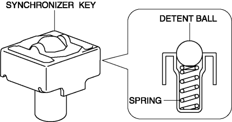
Detent ball-type synchronizer key
-
A detent ball-type synchronizer key has been adopted for the synchronizer mechanism except for the reverse gear.
-
The detent ball of this part provides the driver a crisp feel which the driver can realize completed gear changes.
-
Because this part is smaller compared to the conventional synchronizer key, it has contributed to the size reduction of the synchronizer mechanism, and also to the shortened length of the primary and secondary shafts.
-
Because the smaller synchronizer mechanism has reduced the stroke amount of the clutch hub sleeve, the stroke of the shift lever in the cabin has been shortened.
Operation
1GR, 2GR operation
NOTE:
-
For 1st and 2nd gears, a triple-cone synchronizer mechanism has been adopted with which a stronger synchronizing force is provided to synchronize the rotation of the clutch hub and the gear.
-
Here, operation during 2GR operation is described as an example.
1. When the clutch hub sleeve moves toward the 2nd gear side, the synchronizer key follows, and the synchronizer key contacts the end surface of the synchronizer ring.
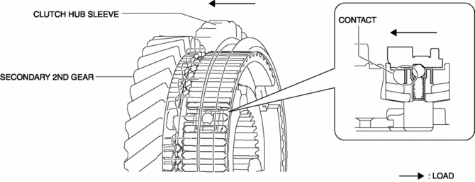
2. When the clutch hub sleeve moves toward the 2nd gear side, the synchronizer key which follows applies load to the synchronizer ring, and the load is transmitted from the synchronizer ring to the middle cone ring, inner cone ring, and the gear.
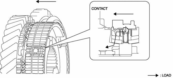
3. The friction force on the contacting surface of the parts is generated by applying load to the parts between the synchronizer ring and the gear.
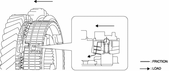
4. For the friction force for the parts, the synchronizer ring rotates only the round groove gap of the clutch hub sleeve.
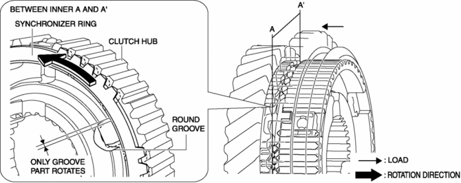
5. Because the synchronizer ring rotates, the spline of the clutch hub sleeve which moves toward the secondary 2nd gear side and the chamfer of the synchronizer ring are opposed to each other.
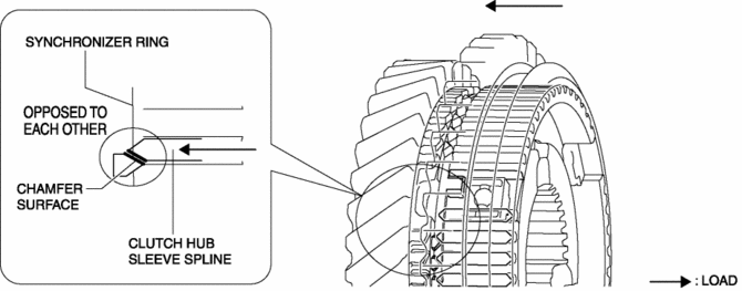
6. When the clutch hub sleeve moves toward the secondary 2nd gear side, the transmitted load to the gear from the clutch hub sleeve increases because the spline of the clutch hub sleeve pushes the chamfer of the synchronizer ring.
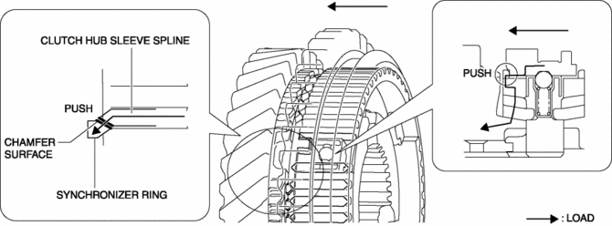
7. The friction force on the contacting surface of the parts is increased by increasing the load transmitted from the clutch hub sleeve to the gear.
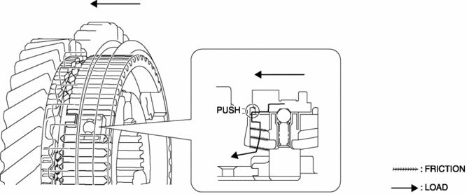
8. The increased friction force decreases the difference in rotation speed between the synchronizer ring, middle cone ring, inner cone ring, and the gear and the rotation speed for the parts is synchronized.
9. When synchronization in rotation speed of the gear and the clutch hub sleeve is performed, the spline of the clutch hub sleeve passes through the synchronizer ring.
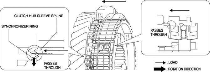
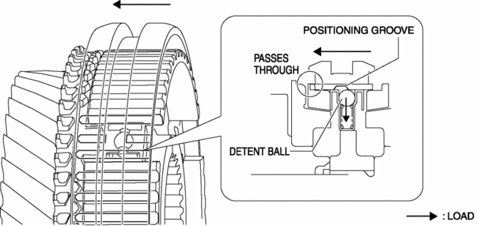
10. When the spline of the clutch hub sleeve passes through the synchronizer ring, the clutch hub sleeve presses down the detent ball and the detent ball is removed from the positioning groove of the clutch hub sleeve because the clutch hub sleeve moves toward the secondary 2nd gear side.
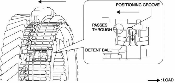
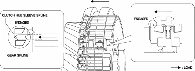
11. When the clutch hub sleeve moves toward the secondary 2nd gear side, the spline of the clutch hub sleeve and the spline of the gear are engaged, and the shifting operation is completed.
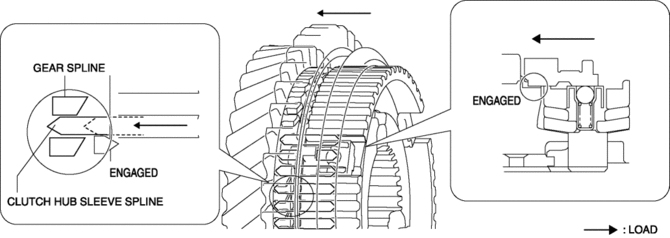
3GR, 4GR, 5GR, 6GR, reverse operation
NOTE:
-
Here, operation during 4GR operation is described as an example.
1. When the clutch hub sleeve moves toward the 4th gear side, the synchronizer key follows, and the synchronizer key contacts the end surface of the synchronizer ring.
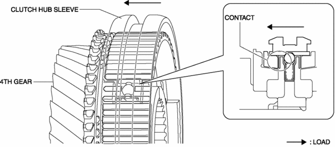
2. When the clutch hub sleeve moves toward the 4th gear side, the following synchronizer key applies load to the synchronizer ring, and the load is transmitted from the synchronizer ring to the gear.
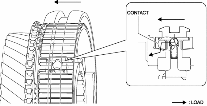
3. The friction force on the contacting surface of the synchronizer ring and the gear is generated by applying load to the parts between the synchronizer ring and the gear.
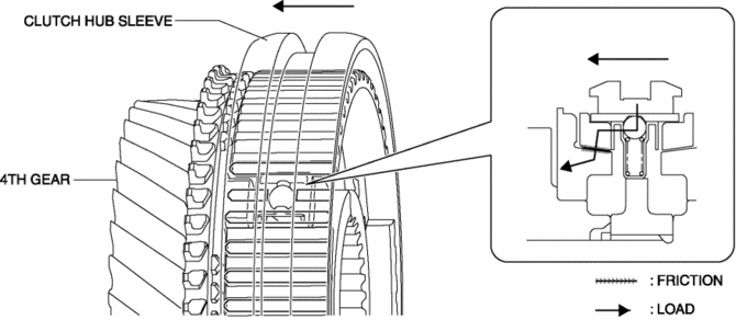
4. For the friction force of the synchronizer ring and the gear, synchronizer ring rotates only the key groove gap of the clutch hub sleeve.
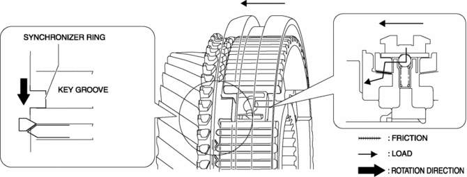
5. Because the synchronizer ring rotates, the spline of the clutch hub sleeve which moves toward the 4th gear side and the chamfer of the synchronizer ring are opposed to each other.
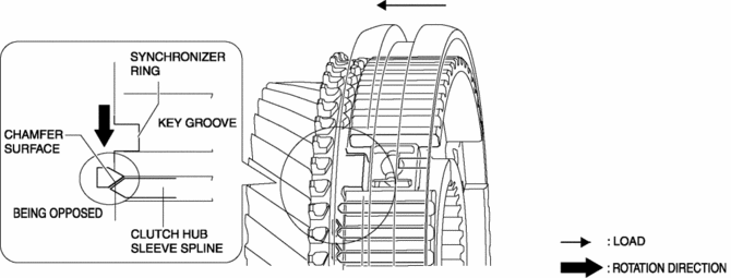
6. When the clutch hub sleeve moves toward the 4th gear, the load transmitted from the clutch hub sleeve to the gear increases because the spline of the clutch hub sleeve pushes the chamfer of the synchronizer ring.
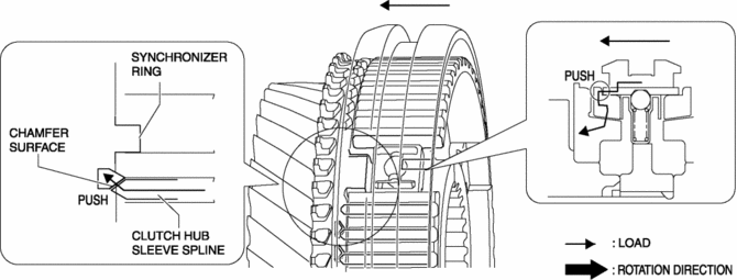
7. The friction force on the contacting surface of the parts is increased by increasing the load transmitted from the clutch hub sleeve to the gear.
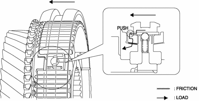
8. The increased friction force disappears the difference in the rotation speed between the synchronizer ring and the gear, and the rotation is synchronized.
9. When synchronization in rotation speed of the gear and the clutch hub sleeve is performed, the spline of the clutch hub sleeve passes through the synchronizer ring.
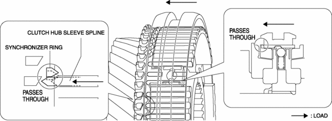
10. When the spline of the clutch hub sleeve passes through the synchronizer ring, the clutch hub sleeve presses down the ball and the ball is removed from the positioning groove of the clutch hub sleeve because the clutch hub sleeve moves toward the secondary 4th gear side.
11. When the clutch hub sleeve moves toward the secondary 4th gear side, the spline of the clutch hub sleeve and the spline of the gear are engaged, and the shifting operation is completed.
 Starter Interlock Switch [Skyactiv G 2.0]
Purpose, Function
The starter interlock switch mechanism prevents vehicle surge when the engine
is started, enhancing safety. The engine cannot be started unless the clutch
is depressed.
...
 TCM Configuration [Fw6 A EL, Fw6 Ax EL]
NOTE:
The TCM is built into the control valve body.
1. Verify TCM configuration implementation necessity for replacement parts.
Replacement part
Conf ...
Other materials:
Location of the Tire Label (Placard)
You will find the tire label containing tire inflation pressure by tire size
and other important information on the driver's side B-pillar or on the edge of
the driver's door frame.
SAMPLE
Recommended Tire Inflation Pressure
On the tire label you will find the recommended tire infla ...
Front Sash Molding Removal
WARNING:
Using a utility knife with bare hands can cause injury. Always wear gloves
when using a utility knife.
1. Using a utility knife, carefully remove the double-sided adhesive tape in
the locations shown below.
CAUTION:
When removing the double-sided adhesive tape, ...
Air Bag Module And Pre Tensioner Seat Belt Deployment Procedures [Standard Deployment
Control System]
WARNING:
A live (undeployed) air bag module or pre-tensioner seat belt may accidentally
operate (deploy) when it is disposed of and cause serious injury. Do not dispose
of a live (undeployed) air bag module or pre-tensioner seat belt. If the SSTs
(Deployment tool and Adapter harness ...
