Mazda CX-5 Service & Repair Manual: Remote Handle Lever Removal/Installation
1. Disconnect the negative battery cable..
2. Remove the following parts:
a. Trunk board.
b. Trunk end trim.
c. Rear scuff plate.
d. Trunk side trim.
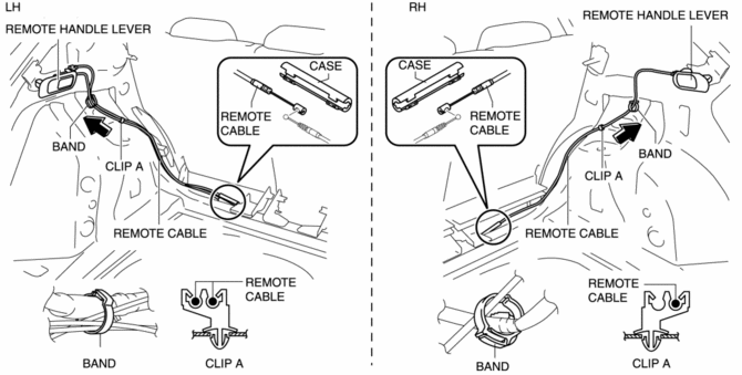
3. Disconnect the remote cable on the remote handle lever side from the remote cable on the rear seat side.

4. Remove the remote cable on the remote handle lever side from the clip.
5. Pull out the remote cable on the remote handle lever side from the band in the direction of the arrow shown in the figure, and remove the remove handle lever.
6. Install in the reverse order of removal..
Remote Handle Lever Installation Note
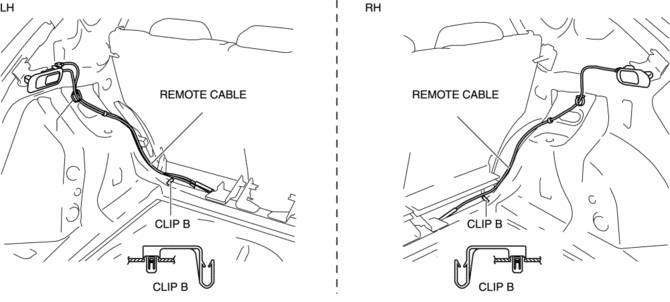
Clip B
CAUTION:
-
Do not use clips B because they were used when the vehicle was manufactured. The remote cables are routed and installed near clips B, however, if the remote cables are installed to clips B, the remote cables may contact the vehicle body while a remote handle lever is operated or the vehicle is driven causing abnormal noise. Therefore, route the remote cables avoiding clips B.

Remote cable
CAUTION:
-
If the remote cables are not routed and installed correctly, it may cause mis-operation of a rear seat back, abnormal noise, or damage to the remote cable. Install the remote cables according to the following procedure.
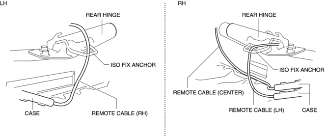
1. Install the remote cables according to the following procedure.
a. Route the remote cables (center) under the rear hinge as shown in the figure.
b. Route the remote cables (LH/RH) through the ISO FIX anchors from top to bottom as shown in the figure.
c. Place the case on the mat behind the rear seat cushion.

2. After installing the remote cables, wobble the rear seat backs forward and back to verify that the rear seat backs are securely locked into the rear seat back strikers.
NOTE:
-
If there is a malfunction in locking, adjust the fixed position of the cable in the case.
 Recliner Motor Inspection
WARNING:
Handling a side air bag improperly can accidentally operate (deploy) the
air bag, which may seriously injure you. Read the service warnings/cautions
in the Workshop Manual befor ...
 Seat
Seat
Outline
Front seat
A manual seat or power seat has been adopted on the driver's seat.
A seat warmer system has been adopted on the front seats. (with seat warmer
system)
...
Other materials:
Wheel Hub Component Removal/Installation [Awd]
CAUTION:
Performing the following procedures without first removing the ABS wheel-speed
sensor may possibly cause an open circuit in the wiring harness if it is pulled
by mistake. Before performing the following procedures, disconnect the ABS wheel-speed
sensor connector (body side) ...
Automatic Transaxle Warning Light [Fw6 A EL, Fw6 Ax EL]
Purpose/Function
The automatic transaxle warning light illuminates when the transaxle has
malfunction.
Construction
The automatic transaxle warning light is built into the instrument cluster.
Operation
If the transmission has a malfunction, the TCM sends an ...
Power Window Regulator
Purpose
The power window regulator moves the carrier plate up and down to open/close
the door glass using the rotation force transmitted from the power window motor.
Function
The power window regulator transmits the rotation force from the power window
motor to the inner wi ...
