Mazda CX-5 Service & Repair Manual: Refrigerant Pressure Sensor Inspection [Full Auto Air Conditioner]
1. Install the manifold gauge.
2. Verify the high-pressure side reading of the manifold gauge.
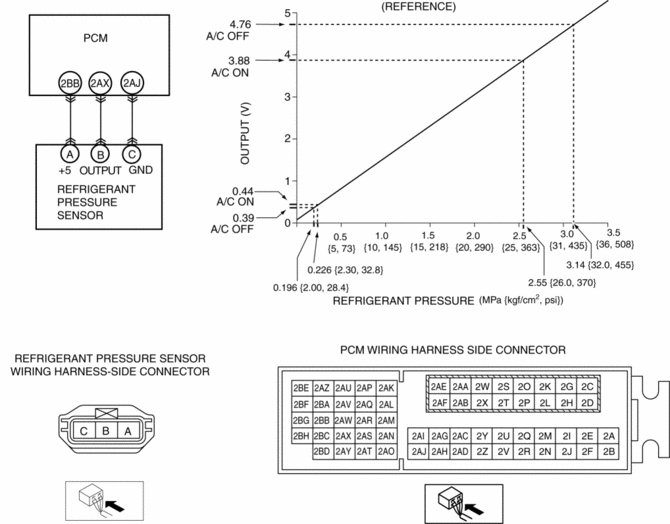
3. Measure the terminal voltage at PCM terminal 2BB, 2AX and 2AJ
4. Using the graph below, measure and verify the terminal voltages at 2AX.
5. Follow the PCM inspection when measuring the other terminal voltages..
-
Terminal 2BB: Approx. 5 V (Ignition switch on)
-
Terminal 2AJ: 1.0 V or less
-
If the each voltage is not normal, inspect the related wiring harness.
-
If there is any malfunction, replace the related wiring harness.
-
If wiring harness is normal, replace the refrigerant pressure sensor.

 Pressure Sensor [Two Step Deployment Control System]
Purpose
The pressure sensor determines at an earlier stage whether to detonate the
air bag on the side of the vehicle (around front door) receiving an impact.
This is for improved accurac ...
 Refrigerant Pressure Sensor Removal/Installation [Full Auto Air Conditioner]
1. Disconnect the negative battery cable..
2. Discharge the refrigerant..
3. Disconnect the refrigerant pressure sensor connector.
CAUTION:
If moisture or foreign material enters the ref ...
Other materials:
Fuel Pump Unit
Purpose, Function
Supplies fuel in the fuel tank to the high pressure fuel pump.
Based on the control signal from the PCM, the fuel pump operates by the operation
of the fuel pump relay and the fuel pump control module.
Construction
2WD
The fuel pump unit is installed ...
Connecting Rod, Connecting Rod Bearing
Purpose, Function
Connecting rod
The connecting rod transmits the reciprocating movement of the piston to
the crankshaft by engaging the piston pin and crank pin.
Connecting rod bearing
The connecting rod bearing forms an oil film on the outer surface of the
crank pin to p ...
Tire Pressure Monitoring System
Tire Pressure Monitoring System
• The Tire Pressure Monitoring System (TPMS)
monitors the air pressure of all four wheels. If the air pressure of one or more
tires is too low, the system warns the driver by indicating the tire pressure monitoring
system warning light in the instrument clust ...
