Mazda CX-5 Service & Repair Manual: Receiver/Drier Removal/Installation
1. Disconnect the negative battery cable..
2. Discharge the refrigerant..
3. Remove the front under cover No.1..
4. Drain the engine coolant..
5. Remove the following parts:
a. Plug hole plate.
b. Air cleaner, air hose and fresh air duct component.
c. Coolant reserve tank.
d. Cooling fan component.
e. Radiator.
6. Remove the condenser..
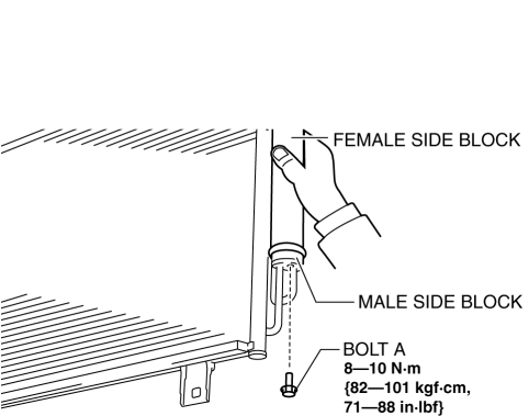
7. Disconnect the block joint type pipes by grasping female side of the block with hand holding firmly then loosen the connection bolt A.
8. Remove bolt B.
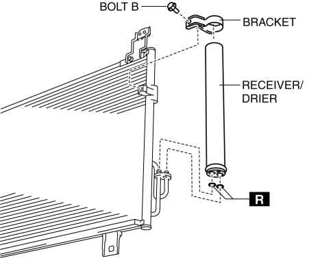
9. Remove the bracket.
10. Remove the receiver/drier. Do not allow compressor oil to spill.
CAUTION:
-
If moisture or foreign material enters the refrigeration cycle, cooling ability will be lowered and abnormal noise will occur. Always immediately plug all open fittings after removing any refrigeration cycle parts to keep moisture or foreign material out of the cycle.
11. Install in the reverse order of removal.
12. Inspect for engine coolant leakage..
13. Perform the refrigerant system performance test..
Receiver/drier Installation Note
1. After replacing the receiver/drier, add compressor oil to the refrigeration cycle.
-
Supplemental oil amount (approx. quantity)
-
2 ml {2 cc, 0.1 fl oz}
 Power Metal Oxide Semiconductor Field Effect Transistor (Power Mos Fet) [Full
Auto Air Conditioner]
Power Metal Oxide Semiconductor Field Effect Transistor (Power Mos Fet) [Full
Auto Air Conditioner]
Purpose
The power MOS FET controls the blower motor rotation speed.
Function
The power MOS FET controls the supply voltage to the blower motor based on
the gate voltage sent fro ...
 Refrigerant Charging
CAUTION:
Do not use a different type of refrigerant or charge beyond the specified
level. Otherwise, cooling ability will be lowered and the A/C compressor could
be damaged.
Chargi ...
Other materials:
Start Stop Unit
Purpose
Performs control of several systems based on input/output signals from switches.
Function
The start stop unit controls systems based on the input/output signals.
The functions which are controlled are as follows:
Control Table
Control ...
Ventilator Grille Removal/Installation
Side Ventilator Grille
Driver-side
1. Disconnect the negative battery cable..
2. Remove the switch panel..
3. Insert your hand from the area where the switch panel was installed, remove
the side ventilator grille in the direction of the arrow shown in the figure while
detaching hooks A.
...
Power Brake Unit
Purpose/Function
A 9.8-inch, single diaphragm type power brake unit has been adopted, achieving
compatibility between high braking performance and excellent brake feeling.
Construction
The power brake unit cannot be disassembled. Therefore, if there is any malfunction
in th ...
