Mazda CX-5 Service & Repair Manual: Rear Wiper System
Outline
-
Equipped with continuous, auto-stop, intermittent wiper, and synchronized washer and wiper operation.
-
The front body control module (FBCM) performs rear wiper and washer system fail-safe..
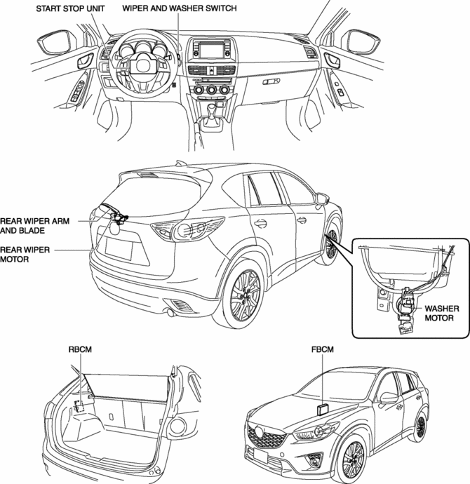
Structural View
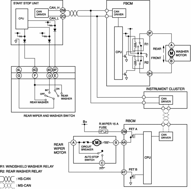
System Wiring Diagram
Operation
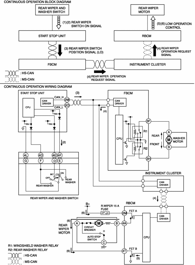
Continuous operation
1. When the rear wiper and washer switch is turned to the ON position with the ignition switched ON (engine off or on) (1), the start stop unit detects a rear wiper switch ON signal.(2)
2. When the start stop unit detects a rear wiper switch ON signal, it send a rear wiper switch position signal (LO) to the front body control module (FBCM) as a CAN signal.(3)
3. When the front body control module (FBCM) receives the rear wiper switch position signal (LO), it sends a rear wiper operation request signal to the rear body control module (RBCM) via the instrument cluster as a CAN signal.(4)
4. When the rear body control module (RBCM) receives the rear wiper operation request signal, it supplies the gate current from the internal CPU to FET B (5), and current flows from the battery to the rear wiper motor and the rear wiper operates continuously.(6)
NOTE:
-
When the ignition is switched ON (engine on or off), the rear body control module (RBCM) turns the FET A on.
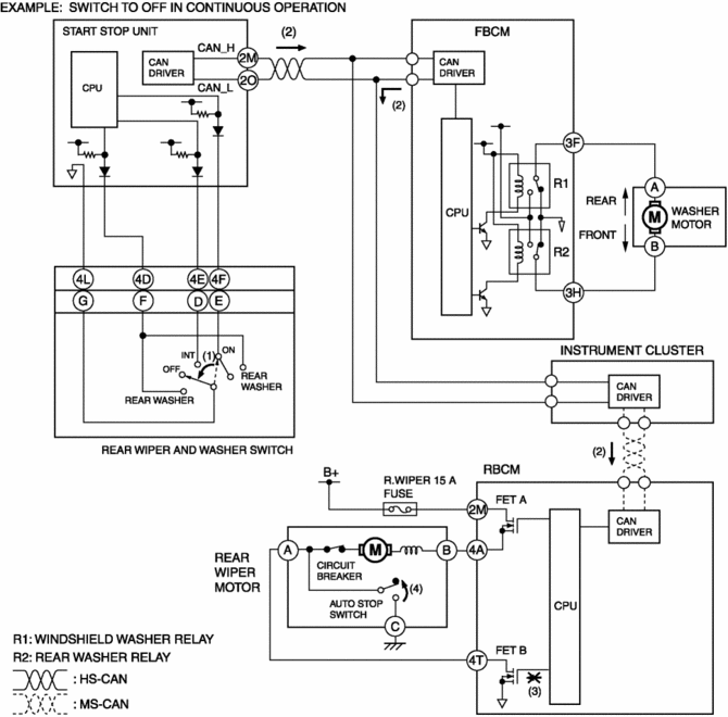
Auto-stop operation
1. If the wiper and washer switch is set to the OFF position (1), the rear wiper operation request signal sent to the rear body control module (RBCM) via the instrument cluster from the front body control module (FBCM) turns off. (2)
2. When the rear wiper operation request signal turns off, the rear body control module (RBCM) turns the FET B off. (3)
3. The autostop switch in the rear wiper motor turns off if the rear wiper stops at the correct position, and the rear wiper stops based on this.(4)
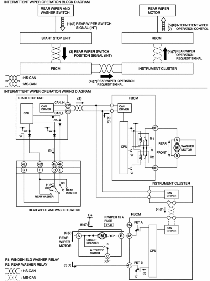
Intermittent wiper operation
1. When the rear wiper and washer switch is moved to the INT position with the ignition switched ON (engine off or on) (1), the start stop unit detects a rear wiper switch signal (INT).(2)
2. When the start stop unit detects a rear wiper switch signal (INT), it send a rear wiper switch position signal (INT) to the front body control module (FBCM) as a CAN signal.(3)
3. When the front body control module (FBCM) receives the rear wiper switch position signal (INT), it sends a rear wiper operation request signal to the rear body control module (RBCM) via the instrument cluster as a CAN signal.(4)
4. When the rear body control module (RBCM) receives the rear wiper operation request signal, it supplies the gate current from the internal CPU to FET B (5), and current flows from the battery to the rear wiper motor and the rear wiper operates.(6)
NOTE:
-
When the ignition is switched ON (engine on or off), the rear body control module (RBCM) turns the FET A on.
5. The front body control module (FBCM) sends a rear wiper operation request signal to the rear body control module (RBCM) via the instrument cluster at regular intervals. Due to this, the rear wiper operates intermittently.(7)
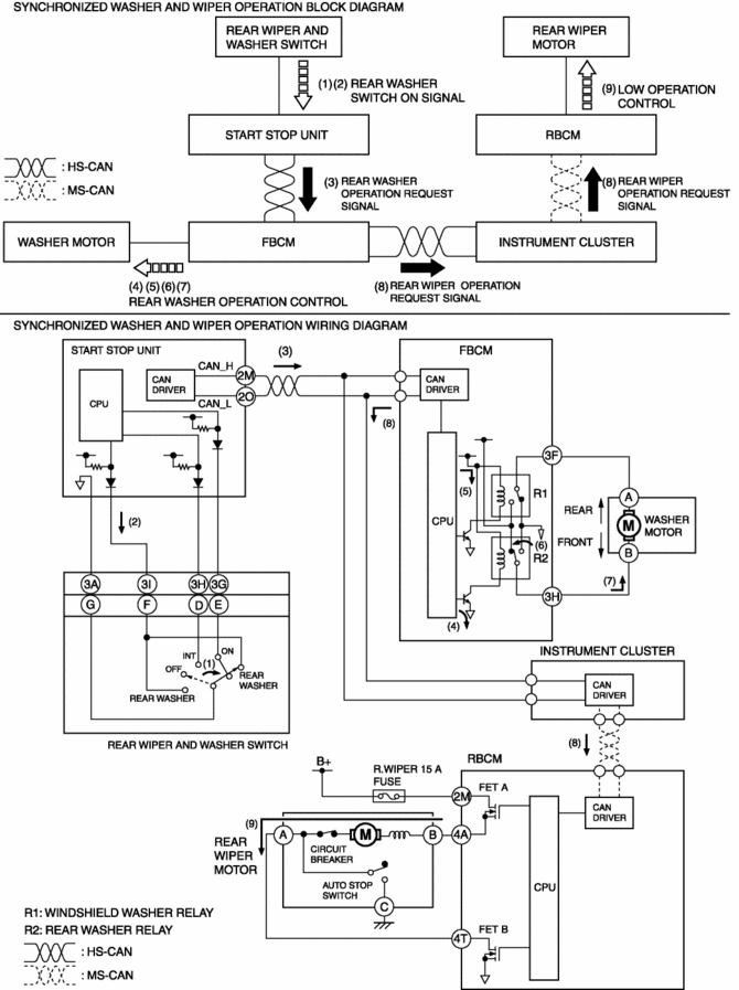
Synchronized washer and wiper operation
1. When the rear wiper and washer switch is turned to the rear washer position with the ignition switched ON (engine off or on) (1), the start stop unit detects a rear washer switch ON signal.(2)
2. When the start stop unit detects a rear washer switch ON signal, it send a rear washer operation request signal to the front body control module (FBCM) as a CAN signal.(3)
3. When the front body control module (FBCM) receives the rear washer operation request signal, it supplies the base current from the internal CPU to transistor (4), and collector current flows from the internal power supply (5), turning the rear washer relay on.(6)
4. When the rear washer relay is turned on, current flows to the washer motor and the washer motor operates, and washer fluid is sprayed from the rear washer nozzle.(7)
5. When the front body control module (FBCM) receives the rear washer operation request signal for a certain period of time, it sends a rear wiper operation request signal to the rear body control module (RBCM) via the instrument cluster as a CAN signal.(8)
6. When the rear body control module (RBCM) receives the rear wiper operation request signal, it operates the rear wiper.(9)
7. When the rear washer switch is turned off, the rear wiper stops after it operates for approx. 2.6 s
.
 Rear Wiper Motor Removal/Installation
1. Disconnect the negative battery cable..
2. Remove the following parts:
a. Rear wiper arm and blade.
b. Liftgate upper trim.
c. Liftgate side trim.
d. Liftgate recess.
e. Liftgate lower ...
 Windshield Wiper Arm And Blade Adjustment
1. Switch the ignition ON (engine off or on).
2. Operate the windshield wiper at low speed.
3. Verify that the windshield wiper operates at low speed and stop the windshield
wiper.
4. Verify t ...
Other materials:
Windshield Wiper Arm And Blade Removal/Installation
Windshield Wiper Arm
1. Open the hood.
CAUTION:
If excessive force is applied when removing the cap, tabs could break. Carefully
remove the cap.
2. Insert a tape-wrapped precision flathead screwdriver into the gap between
the windshield wiper arm and cap, and slightly raise the ...
Liftgate Garnish Removal/Installation
1. Disconnect the negative battery cable..
2. Remove the following parts:
a. Liftgate upper trim.
b. Liftgate side trim.
c. Liftgate recess.
d. Liftgate lower trim.
3. Disconnect the connectors.
4. Remove nuts A.
5. Detach clips B shown in the figure.
6. Remove the liftgate ...
Air Intake Actuator [Manual Air Conditioner]
Purpose
The air intake actuator moves the air intake door in the blower unit to switch
the air intake port.
Function
The air intake actuator drives the motor based on the signal from the climate
control unit and moves the air intake door to the FRESH or REC position.
...
