
Mazda CX-5 Service & Repair Manual: Rear Seat Cushion Trim Removal/Installation
CAUTION:
-
When removing or putting in the rear seat cushion, contact with the surrounding areas of the vehicle could cause scratches and damage. When removing or putting in the rear seat cushion, always use two or more persons to perform the work and be careful not to scratch or damage the rear seat cushion and the surrounding area of the vehicle.
-
When performing the procedure with a rear seat cushion removed from the vehicle, perform the procedure on a clean cloth so as not to damage or soil the seat.
6:4 Split Type
1. Remove the rear seat cushion.
2. Slide hooks A in the order of (1), (2) shown in the figure to detach it from the rear seat cushion pad.
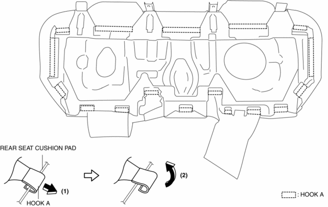
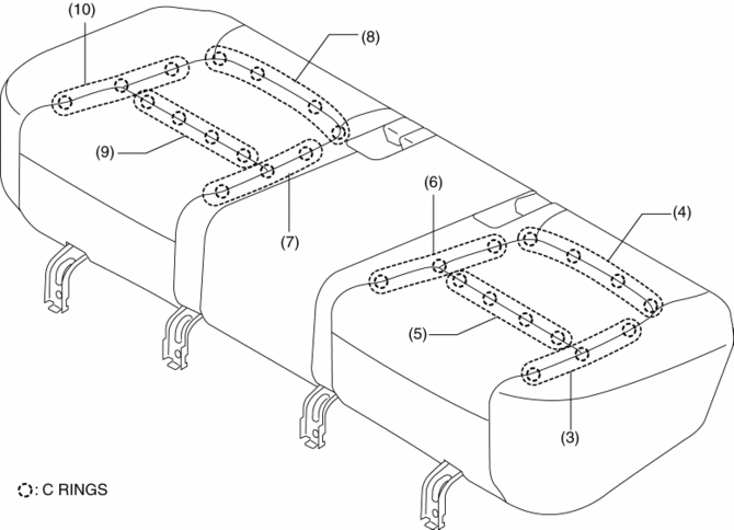
3. Partially peal back the rear seat cushion trim from the rear seat cushion pad, remove C rings in the order of (3), (4), (5), (6), (7), (8), (9), (10) shown in the figure,
CAUTION:
-
If a damaged C rings are reused, it may not be possible to install the rear seat cushion trim and rear seat cushion pad correctly. When removing and installing C rings, be careful not to damage them.
-
If a C rings are damaged, replace the C rings with a new one.
4. Install in the reverse order of removal.
4:2:4 Split Type
1. Remove the trunk board..
2. Remove the rear seat..
3. Slide hooks A in the order of (1), (2) shown in the figure to detach it from the rear seat cushion pad.
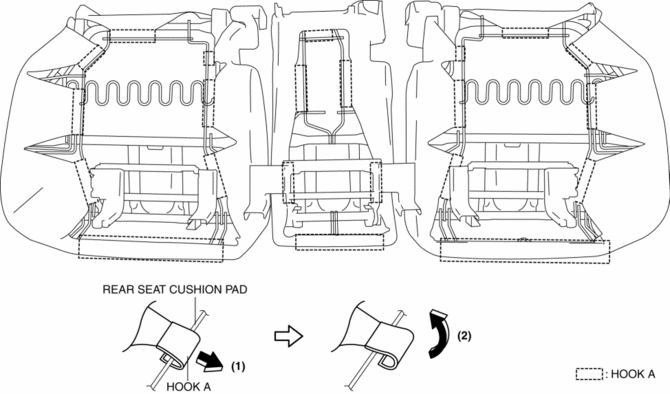
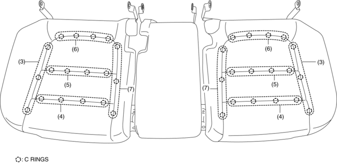
4. Partially peal back the rear seat cushion trim from the rear seat cushion pad, remove C rings in the order of (3), (4), (5), (6), (7) shown in the figure,
CAUTION:
-
If a damaged C rings are reused, it may not be possible to install the rear seat cushion trim and rear seat cushion pad correctly. When removing and installing C rings, be careful not to damage them.
-
If a C rings are damaged, replace the C rings with a new one.
5. Install in the reverse order of removal.
 Rear Seat Cushion Removal/Installation
CAUTION:
When removing or putting in the rear seat cushion, contact with the surrounding
areas of the vehicle could cause scratches and damage. When removing or putting
in the rear seat ...
 Rear Seat Removal/Installation
CAUTION:
When removing or putting in the rear seat, contact with the surrounding areas
of the vehicle could cause scratches and damage. When removing or putting in
the rear seat, always ...
Other materials:
Rear Fender Lower Panel Installation [Panel Replacement]
Symbol Mark
Installation Procedure
1. When installing new parts, measure and adjust the body as necessary to conform
with standard dimensions.
2. After temporarily installing new parts, make sure the related parts fit properly.
3. Spot weld the 26 locations shown in the figure, then ins ...
Bumper Bracket Removal [Panel Replacement]
Symbol Mark
Removal Procedure
1. Rough cut area locations indicated by (A).
2. Grind the 6 locations indicated by (B) shown in the figure.
CAUTION:
When grinding 6 locations indicated by (B) shown in the figure and the front
side frame is damaged, there is a possibility that ...
Rollover Valve
Purpose, Function
Prevents fuel from flowing into the evaporative gas passage during sudden
cornering or vehicle rollover.
Construction
The rollover valve is built into the fuel tank.
U.S.A. and CANADA
Except U.S.A. and CANADA
The rollover valve con ...
