Mazda CX-5 Service & Repair Manual: Positive Crankcase Ventilation (PCV) Valve Inspection
Airflow Inspection
1. Disconnect the section (A) of ventilation hose shown in the figure.
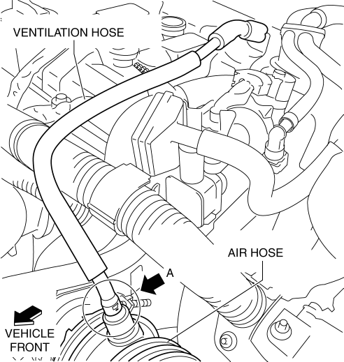
2. Start the engine and verify that vacuum is applied to the end of the disconnected ventilation hose while the engine is idling.
-
If vacuum is not applied to the ventilation hose, perform the procedure from Step 3.
NOTE:
-
If the PCV valve is operating normally, vacuum occurs in the ventilation hose, however, if the PCV valve is not operating normally, vacuum does not occur in the ventilation hose because the blow-by gas is circulated to the air hose from the ventilation hose.
-
Verify the ventilation hose vacuum as follows:
-
When the tip of your figure is touching the end of the ventilation hose, the tip of your figure is suctioned by the hose.
-
When a thin scrap of paper is contacting the end of the ventilation hose. the paper is suctioned by the hose.
3. Disconnect the negative battery cable..
4. Remove the intake manifold..
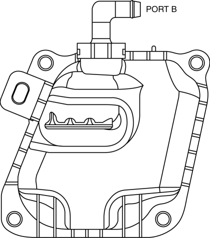
5. Remove the PCV valve and the oil separator as a single unit..
6. Verify that there is no airflow when pressure is applied to port B.
-
If there is airflow, replace the PCV valve and the oil separator as a single unit..
7. Verify that there is airflow when vacuum is applied to port B.
-
If there is no airflow, replace the PCV valve and the oil separator as a single unit..
 Positive Crankcase Ventilation (PCV) System
Purpose, Outline
Prevents release of blow-by gas (unburnt gas) into the atmosphere.
The intake manifold vacuum introduces blow-by gas to the intake manifold
via the PCV valve and the ...
 Positive Crankcase Ventilation (PCV) Valve Removal/Installation
1. Disconnect the negative battery cable..
2. Remove the intake manifold..
3. Remove in the order indicated in the table.
4. Install in the reverse order of removal.
1
...
Other materials:
Engine Oil Pressure Warning Light
Purpose
The engine oil pressure warning light warns the driver that the engine oil
level is insufficient.
Function
When the instrument cluster receives the engine oil pressure warning light
request signal sent from the PCM via the CAN signal, it illuminates the engine
oi ...
Interior Care
WARNING
Do not spray water in the cabin:
Splashing water on electrical parts such as the audio unit and switches is dangerous
as it could cause a malfunction or a fire.
Dashboard Precautions
Prevent caustic solutions such as perfume and cosmetic oils from contacting the
dashboard. They will ...
Engine Mount
Purpose, Function
The engine mount secures the engine and transaxle to the vehicle body, reducing
vibration and noise.
Construction
The three points at the engine front (No.3 engine mount), one side of the
transaxle (No.1 engine mount), and the rear upper part of the transa ...
