Mazda CX-5 Service & Repair Manual: Clutch Pipe And Hose Removal/Installation [C66 M R]
CAUTION:
-
Do not allow clutch fluid to get on a painted surface. Clutch fluid contains properties which can dissolve the paint. If clutch fluid gets on a painted surface, wash it off with water immediately and wipe the area off completely.
1. Disconnect the negative battery cable..
2. Remove the air cleaner component. (ex: air cleaner, air hose).
3. Remove the battery component. (ex: battery, battery tray and PCM component).
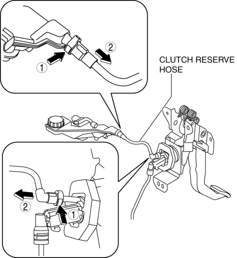
4. Remove the clutch reserve hose while pressing the point indicated by the arrow in the figure.

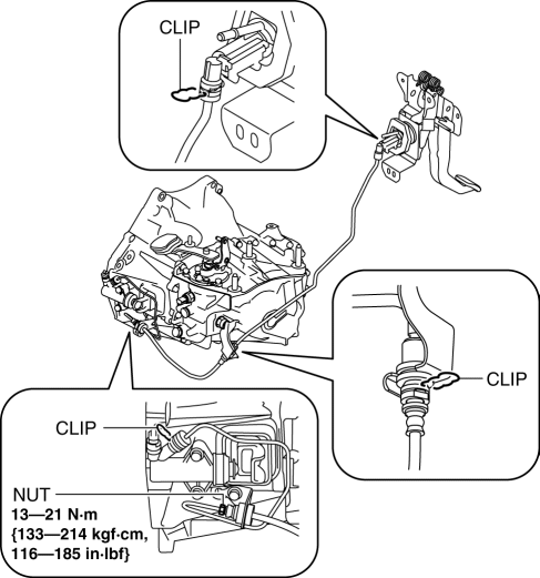
5. Remove the clutch pipe and hose (No.1 and No.2) using the following procedure:

a. Lift the connector clip.
b. Pull out the clutch pipe and hose (No.1 and No.2) connector straight to detach it.
c. Remove the clutch pipe and hose (No.1 and No.2).
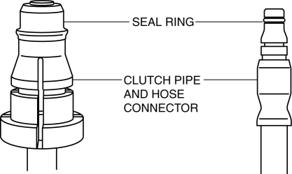
6. Verify that the seal ring is installed to the clutch pipe and hose connector.

CAUTION:
-
When removing the clutch pipe and hose, the seal ring for the clutch pipe and hose could remain on the receiving area of the connector. If the clutch pipe and hose is assembled under this condition, it could cause clutch fluid leakage from the connector.
7. Install the clutch pipe and hose (No.1 and No.2).
a. Press in the connector clip.
b. Insert the clutch pipe and hose (No.1 and No.2) connector straight.
NOTE:
-
When the connector is engaged, a click sound is heard.
c. Install the clutch pipe and hose (No.1 and No.2).
8. Insert the clutch reserve hose connector straight.
NOTE:
-
When the connector is engaged, a click sound is heard.
9. Pull each engagement of the clutch reserve hose and clutch pipe and hose No.1 and 2, verify that they are engaged, and then press all of them again.
10. Install in the reverse order of removal.
11. Bleed the air from the clutch system..
 Clutch Pedal Removal/Installation [C66 M R]
CAUTION:
Secure the steering wheel using tape or a cable to prevent the steering shaft
from rotating after disconnecting the steering shaft. If the steering wheel
rotates after the steer ...
 Clutch Release Collar Inspection [C66 M R]
CAUTION:
Do not clean the clutch release collar with cleaning fluids or a steam cleaner
because it is filled with grease.
Operation Inspection
1. Turn the collar while applying force ...
Other materials:
Wheel Hub Component Removal/Installation [2 Wd]
CAUTION:
Performing the following procedures without first removing the ABS wheel-speed
sensor may possibly cause an open circuit in the wiring harness if it is pulled
by mistake. Before performing the following procedures, disconnect the ABS wheel-speed
sensor connector (body sid ...
Keyless Warning Alarm
Purpose
The keyless warning alarm notifies the driver that the remote transmitter
cannot be verified or the steering lock cannot be released.
Function
When the instrument cluster receives the keyless warning alarm request signal
sent from the start stop unit via the CAN sig ...
Antenna Feeder No.3 Removal/Installation
1. Disconnect the negative battery cable..
2. Remove the following parts:
a. B-pillar lower trim.
b. Front seat belt adjusting cover.
c. Front seat belt upper anchor installation bolt.
d. B-pillar upper trim.
e. Trunk board.
f. Trunk end trim.
g. Trunk side trim.
h. D-pillar trim. ...
