Mazda CX-5 Service & Repair Manual: Liftgate Light
Purpose
-
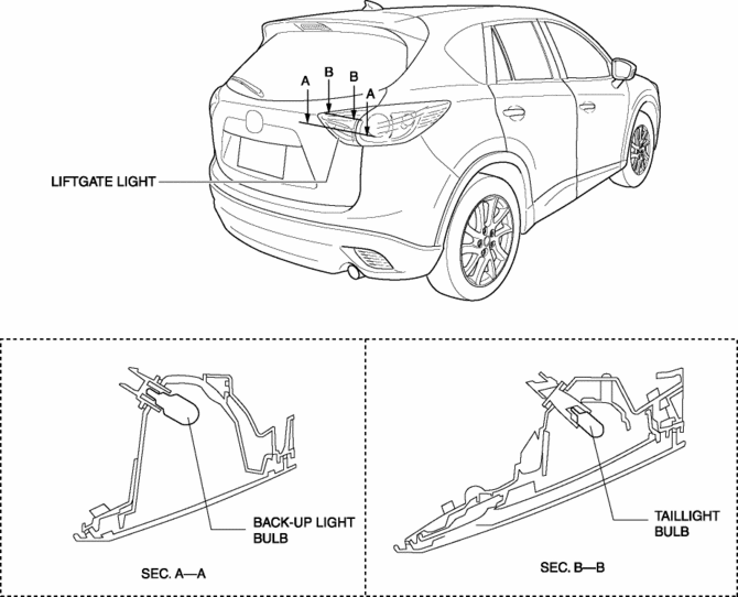
The liftgate lights are used to signal the following conditions to vehicles/people at the rear.
-
Back-up lights: Signals that the vehicle is backing up.
-
Taillights: Signals the presence of the vehicle during nighttime.
Function
-
The back-up lights are illuminated in conjunction with the shift operation.
-
The taillights are illuminated in conjunction with the light switch operation (TNS).
Construction
-
The following parts are an integrated structure.
-
Back-up light
-
Taillight
-
A clear lens has been adopted for the liftgate light.
NOTE:
-
Fogging or condensation may occur inside the liftgate lights, however, it is a natural phenomenon occurring as a result of a temperature difference between the interior and exterior of the liftgate lights and has no effect on the light performance. Fogging or condensation will dissipate when the temperature inside the liftgate lights rises after the back-up light bulb is illuminated and a period of time has elapsed.

Operation
Taillights
1. When the light switch is operated to the TNS position, a TNS signal is input to the start stop unit.
2. The start stop unit sends the TNS signal to the front body control module (FBCM).
3. When the front body control module (FBCM) receives the TNS signal, it turns the TNS relay on.
4. When the TNS relay turns on, the taillight bulbs are illuminated.

Buck-up lights (MTX)
1. When the shift lever is operated to the R position, the back-up light switch is turned on.
2. When the back-up light switch is turned on, a back-up light on signal is input to the PCM.
3. The PCM sends the back-up light switch on signal to the instrument cluster.
4. The instrument cluster sends the back-up light switch on signal to the rear body control module (RBCM).
5. When the rear body control module (RBCM) receives the back-up light switch on signal, the back-up lights are illuminated.

Buck-up lights (ATX)
1. When the selector lever is operated to the R position, the TCM sends an R position signal to the PCM.
2. When the PCM receives the R position signal, it sends a back-up light on signal to the instrument cluster.
3. The instrument cluster sends the back-up light switch on signal to the rear body control module (RBCM).
4. When the rear body control module (RBCM) receives the back-up light on signal, the back-up lights are illuminated.

Fail-safe
-
Function not equipped.
 Liftgate Latch Switch Inspection
1. Disconnect the negative battery cable..
2. Remove the following parts:
a. Liftgate upper trim.
b. Liftgate side trim.
c. Liftgate lower trim.
d. Liftgate latch and lock actuator.
3. Ver ...
 Liftgate Light Removal/Installation
NOTE:
Fogging or condensation on the inside of the liftgate light may occur, however,
it is a natural phenomenon occurring as a result of a temperature difference
between the interior an ...
Other materials:
Hydraulic Lash Adjuster (Hla) Inspection
HLA Troubleshooting
Item
Occurrence
Possible cause
Action
1
After replacing oil, sound occurs when starting engine
Oil shortage in oil passage
Maintain the engine speed between 2,000 ...
Power Window Subswitch
Purpose
Each door glass except for the driver-side can be opened/closed with occupant
seated in the cabin using the power window subswitch.
Function
Manual switch
The power window subswitch switches the contact point according to the switch
operation and switches the circu ...
Timing Chain, Chain Tensioner
Purpose, Function
Timing chain
The timing chain transmits the rotation force of the crankshaft to the camshaft
to perform the rotation timing of the crankshaft and camshaft.
Chain tensioner
The chain tensioner constantly maintains the timing chain tension and the
timing ch ...
