
Mazda CX-5 Service & Repair Manual: Fuel Pump Unit Disassembly/Assembly
WARNING:
-
Fuel is very flammable liquid. If fuel spills or leaks from the pressurized fuel system, it will cause serious injury or death and facility breakage. Fuel can also irritate skin and eyes. To prevent this, always complete the “Fuel Line Safety Procedure”, while referring to “BEFORE SERVICE PRECAUTION”.
-
A person charged with static electricity could cause a fire or explosion, resulting in death or serious injury. Before draining fuel, make sure to discharge static electricity by touching the vehicle body.
CAUTION:
-
Disconnecting/connecting the quick release connector without cleaning it may cause damage to the fuel pipe and quick release connector. Always clean the quick release connector joint area before disconnecting/connecting using a cloth or soft brush, and make sure that it is free of foreign material.
1. Complete the “BEFORE SERVICE PRECAUTION”..
2. Using the following procedure:
CAUTION:
-
Because the fuel surface is higher than the fuel pump unit installation surface, if the set plate is removed, it may result in fuel leakage. If the fuel gauge level indicates 1/2 or more, refer to the fuel draining procedure and drain 20 liters of fuel.
-
Fuel gauge indicates 1/2 or more
-
Drain the fuel..
-
Fuel gauge indicates less than 1/2
-
Disconnect the negative battery cable..
3. Remove the following part:
-
6:4 split type
-
Remove the rear seat cushion..
-
4:2:4 split type
-
Set the rear seat aside as shown in the figure..
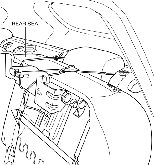
4. Remove the fuel pump unit..
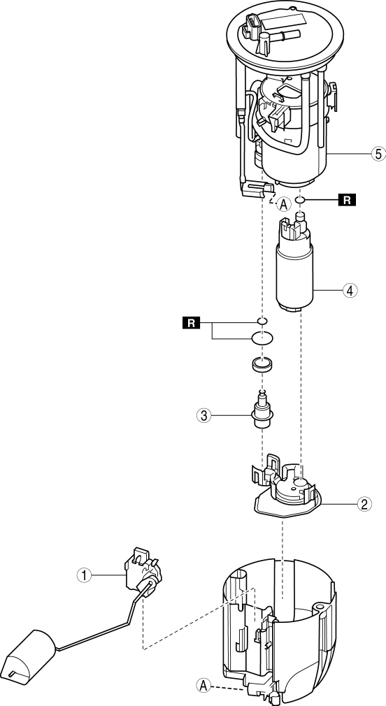
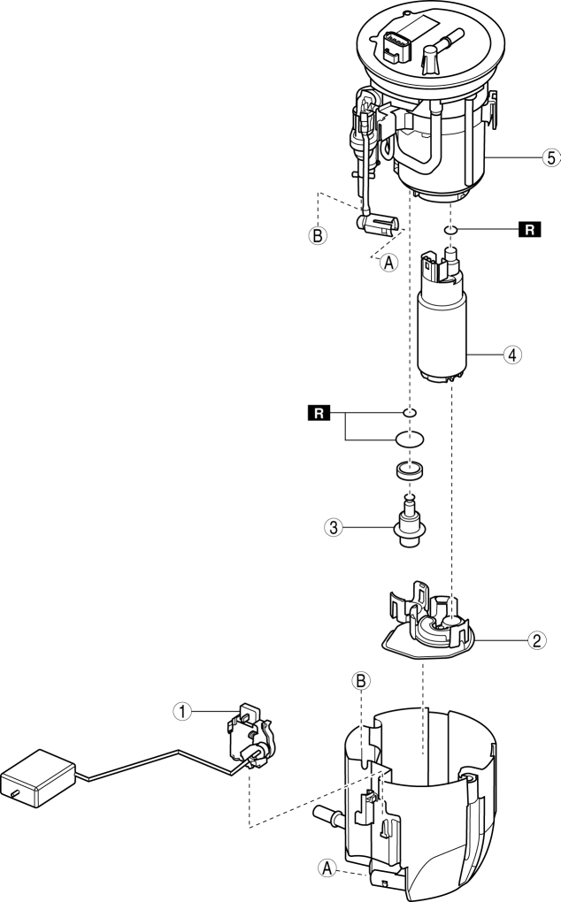
5. Disassemble in the order indicated in the table.
6. Assemble in the reverse order of disassembly.
7. Install in the reverse order of removal.
8. Complete the “AFTER SERVICE PRECAUTION”..
2WD
|
1 |
Fuel gauge sender unit |
|
2 |
Fuel filter (low-pressure) |
|
3 |
Pressure regulator |
|
4 |
Fuel pump |
|
5 |
Fuel filter (high-pressure) |
AWD
|
1 |
Fuel gauge sender unit |
|
2 |
Fuel filter (low-pressure) |
|
3 |
Pressure regulator |
|
4 |
Fuel pump |
|
5 |
Fuel filter (high-pressure) |
 Fuel Pump Control
Outline
By switching the fuel pump discharge amount, reduced power consumption and
improved fuel economy have been realized.
The PCM determines the optimum fuel pump drive force acco ...
 Fuel Pump Unit Inspection
Continuity Inspection
1. Disconnect the negative battery cable..
2. Disconnect the fuel pump unit connector.
3. Inspect for continuity between fuel pump unit terminals B—D.
If there ...
Other materials:
Rear Sash Molding Installation
WARNING:
Using a utility knife with bare hands can cause injury. Always wear gloves
when using a utility knife.
NOTE:
Double-sided adhesive tape has already been attached to the new rear sash
molding.
1. When installing a new rear sash molding, follow the procedure ...
Front Seat Belt Pretensioner and Load Limiting Systems
For optimum protection, the driver and front passenger seat belts are equipped
with pretensioner and load limiting systems. For both these systems to work properly
you must wear the seat belt properly.
Pretensioners:
In moderate or severe frontal or nearfrontal accidents, the front air bag and ...
Rear Drive Shaft
Purpose, Function
Engine noise and vibration have been reduced due to adoption of a bell joint
on the wheel side of the constant velocity joint.
A low noise and vibration double offset joint with low slide resistance has
been adopted for the differential side of the constant vel ...
