Mazda CX-5 Service & Repair Manual: Fuel Gauge Sender Unit Removal/Installation [Awd]
WARNING:
-
Always keep sparks and flames away from fuel when servicing the fuel system. Fuel can be easily ignited which could cause serious injury or death, and damage to equipment.
-
Fuel line spills and leakage from the pressurized fuel system are dangerous. Fuel can ignite and cause serious injury or death and damage. Fuel can also irritate skin and eyes. To prevent this, always complete the Fuel Line Safety Procedure, while referring to the BEFORE SERVICE PRECAUTION.
-
A person charged with static electricity could cause a fire or explosion, resulting in death or serious injury. Before draining fuel, make sure to discharge static electricity by touching a vehicle.
CAUTION:
-
If the fuel gauge level indicates 3/4 or more, the fuel surface is higher than the fuel pump unit and fuel gauge sender unit installation surface. If servicing is performed under this condition, fuel leakage could result. Always drain the fuel before performing the operation and keep the fuel in the fuel tank at less than half.
Fuel Gauge Sender Unit (main)
NOTE:
-
For the fuel gauge sender unit removal/installation, refer to the fuel pump removal/installation because the fuel gauge sender unit is integrated with the fuel pump..
Fuel Gauge Sender Unit (sub)
1. Perform the "Fuel Line Safety Procedure" referring to the "BEFORE REPAIR PROCEDURE"..
2. If the fuel gauge level indicates 3/4 or more, refer to the "FUEL DRAINING PROCEDURE" and drain the fuel..
3. Remove the following parts:
a. Rear seat cushion (6:4 split type).
b. Rear seat under installation bolt (4:2:4 split type).
c. Rear scuff plate.
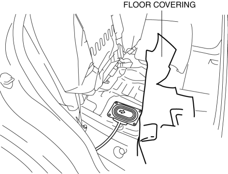
4. Partially peel back the floor covering.
5. Remove the screws.
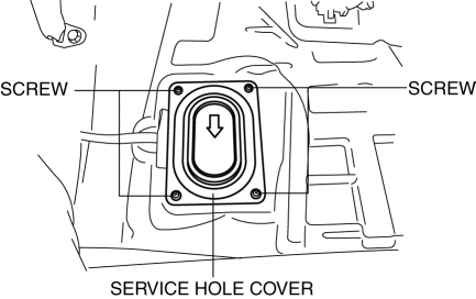
6. Remove the service hole cover.
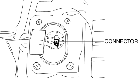
7. Disconnect the connector.
8. Remove the screws.
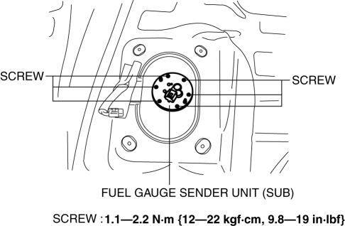
9. Remove the fuel gauge sender unit (sub).
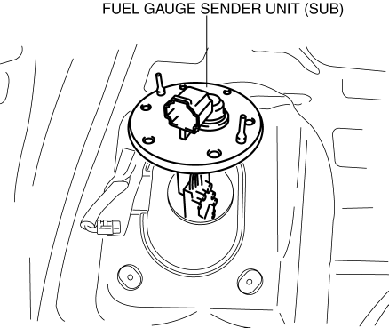
10. Install in the reverse order of removal.
11. Perform the fuel leakage inspection referring to [AFTER SERVICE PRECAUTION]..
 Fuel Gauge Sender Unit Removal/Installation [2 Wd]
WARNING:
Always keep sparks and flames away from fuel when servicing the fuel system.
Fuel can be easily ignited which could cause serious injury or death, and damage
to equipment.
...
 Odometer/Tripmeter
Purpose
The odometer/tripmeter notifies the user of the total travel distance or
the traveled distance over a specific interval.
Function
The instrument cluster calculates the t ...
Other materials:
Outer Mirror Garnish Removal/Installation
1. Disconnect the negative battery cable..
2. Remove the outer mirror glass..
3. Insert a tape-wrapped flathead screwdriver into the upper outer mirror garnish
and remove tab A, B, C, D in the direction of arrow (1).
4. Insert a tape-wrapped flathead screwdriver into the upper outer mirr ...
Door Lock Switch Inspection
Driver's Side
1. Disconnect the negative battery cable..
2. Remove the door lock switch..
3. Verify that the continuity is as indicated in the table.
If the continuity is not as indicated in the table, replace the door lock
switch.
Passenger's Side
1. Disconnec ...
Driver Side Air Bag Module Removal/Installation [Standard Deployment Control
System]
WARNING:
Handling the air bag module improperly can accidentally deploy the air bag
module, which may seriously injure you. Read the air bag system service warnings
and cautions before handling the air bag module..
NOTE:
The driver-side air bag module is installed to the ...
