Mazda CX-5 Service & Repair Manual: Fuel Gauge Sender Unit Inspection [2 Wd]
NOTE:
-
For the fuel gauge sender unit removal/installation, refer to the fuel pump removal/installation because the fuel gauge sender unit is integrated with the fuel pump..
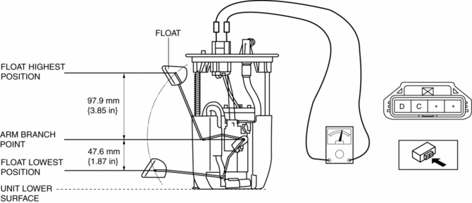
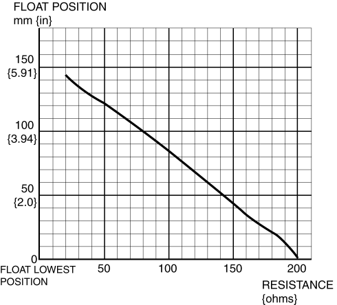
1. Verify that the resistance at fuel gauge sender unit terminals D and C is as indicated in the table according to the height of the float.


-
If not as indicated in the table, replace the fuel gauge sender unit.
 Fuel Gauge
Purpose
The fuel gauge notifies the user of the amount of remaining fuel.
Function
The instrument cluster calculates the amount of fuel in the fuel tank based
on the following C ...
 Fuel Gauge Sender Unit Inspection [Awd]
Fuel gauge sender unit (main)
NOTE:
For the fuel gauge sender unit removal/installation, refer to the fuel pump
removal/installation because the fuel gauge sender unit is integrated with t ...
Other materials:
Towing
Trailer Towing (U.S.A. and Canada)
Your Mazda was designed and built primarily to carry passengers and cargo.
If you tow a trailer, follow these instructions because driver and passenger
safety depends on proper equipment and safe driving habits. Towing a trailer will
affect handling, braking, ...
Air Bag Module And Pre Tensioner Seat Belt Disposal Procedures [Two Step Deployment
Control System]
WARNING:
A live (undeployed) air bag module, pre-tensioner seat belt or lap pre-tensioner
seat belt may accidentally operate (deploy) when it is disposed of and cause
serious injury. Always refer to the “AIR BAG MODULE AND PRE-TENSIONER SEAT BELT
DEPLOYMENT PROCEDURES” and dispo ...
Seat Weight Sensor Control Module Removal/Installation [Two Step Deployment
Control System]
CAUTION:
When the seat weight sensor control module is replaced with a new one, perform
the seat weight sensor calibration using the M?MDS..
1. Switch the ignition to off.
2. Disconnect the negative battery cable and wait for 1 min or more..
3. Disconnect the connectors.
...
