Mazda CX-5 Service & Repair Manual: Fuel Gauge
Purpose
-
The fuel gauge notifies the user of the amount of remaining fuel.
Function
-
The instrument cluster calculates the amount of fuel in the fuel tank based on the following CAN signals and displays the fuel gauge segments.
-
Fuel gauge sender unit voltage signal sent from rear body control module (RBCM)
-
Fuel injection amount signal, vehicle speed signal sent from PCM
Fuel gauge flicker prevention function
-
When the instrument cluster determines that the vehicle is being driven, it retards the response with which the calculated amount of fuel is reflected to the fuel gauge. As a result, fuel gauge flicker caused by the variation of fuel surface during driving is prevented.
Refuel determination function
-
If the amount of fuel is changed by 5 L {1 US gal, 1 Imp gal}/2 L {0.5 US gal, 0.4 Imp gal}*1 or more while the vehicle is stopped, the instrument cluster determines that the vehicle is refueled and displays the fuel gauge segments based on the fuel gauge sender unit voltage signal from the rear body control module (RBCM).
Construction
-
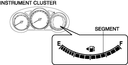
The fuel gauge is displayed in the LCD of the instrument cluster.
-
The fuel gauge is consists of 15 segments.
Operation
-
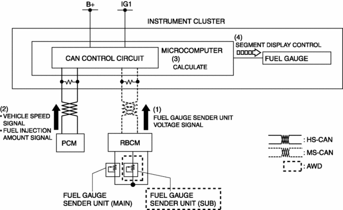
When the ignition is switched ON (engine off or on), the rear body control module (RBCM) converts the resistance from the fuel gauge sender unit to voltage and sends it to the instrument cluster as a fuel gauge sender unit voltage signal (1).
-
The instrument cluster receives the fuel gauge sender unit voltage signal from the rear body control module (RBCM), and it also receives the fuel injection amount signal and vehicle speed signal from the PCM (2).
-
The instrument cluster calculates the amount of fuel in the fuel tank based on the signals (3).
-
The instrument cluster displays/turns off the fuel gauge segments according to the calculation result (4).
Fail-safe
-
Function not equipped.
 Ambient Temperature Display Switching Procedure
NOTE:
When the ambient temperature display is switched, the set A/C cabin temperature
display is also changed.
...
 Fuel Gauge Sender Unit Inspection [2 Wd]
NOTE:
For the fuel gauge sender unit removal/installation, refer to the fuel pump
removal/installation because the fuel gauge sender unit is integrated with the
fuel pump..
1. Veri ...
Other materials:
Condenser Removal/Installation
1. Disconnect the negative battery cable..
2. Remove the following parts:
a. Trunk board.
b. Trunk end trim (LH).
c. Rear scuff plate (LH).
d. Trunk side trim (LH).
e. D-pillar trim (LH).
3. Disconnect the connector.
4. Remove the bolts.
5. Remove the condenser.
6. Install in ...
Start Stop Unit Configuration (Using Read/Write Function)
NOTE:
When performing configuration, it is necessary to read the vehicle specification
information from the start stop unit before replacing it. Connect the M-MDS
to the vehicle and perform vehicle identification before removing the start
stop unit. The vehicle specification informa ...
Hydraulic Lash Adjuster (Hla) Removal/Installation
WARNING:
A hot engine can cause severe burns. Turn off the engine and wait until it
is cool before servicing.
CAUTION:
If the camshaft is rotated with the timing chain removed and the piston at
the top dead center position, the valve may contact the piston and the engine ...
