
Mazda CX-5 Service & Repair Manual: Front Sash Molding Installation
WARNING:
-
Using a utility knife with bare hands can cause injury. Always wear gloves when using a utility knife.
NOTE:
-
Double-sided adhesive tape has already been attached to the new front sash molding.
1. When installing a new front sash molding, follow the procedure below:
a. Carefully remove the adhesive remaining on the body using a razor blade.
b. Remove any grease or dirt from the adhesion surface of the body.
2. Remove the adhesive remaining on the front sash molding and the body using a razor blade.
a. Remove any grease or dirt from the adhesion surface of the front sash molding and the body.
b. Apply primer to the bonding area of the front sash molding.
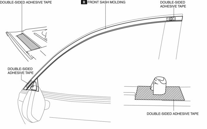
c. Affix double-sided adhesive tape to the front sash molding as shown in the figure.
NOTE:
-
As for the double-sided adhesive tape, use 3M GT7120 or equivalent.
3. Peel off the backing of the double-sided adhesive tape.
4. Hook tab A to the body in the position where clip B aligns with the sash holes.
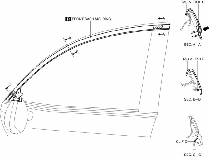
5. Press the front sash molding in the direction of the arrow and install clip B to the body.
CAUTION:
-
Do not press the front sash molding in any place other than the rubber areas.
6. Press the front sash molding from the vehicle front in the direction of the arrow and install tab C.
7. Press the front sash molding in the direction of the arrow and install clip D to the body.
NOTE:
-
After installing the front sash molding, verify that tabs A and C are connected properly to the body.
 Front Door Trim Removal/Installation
1. Disconnect the negative battery cable..
2. Remove the inner garnish..
3. Insert a tape-wrapped flathead screwdriver in the position indicated by the
arrow (1) in the figure and remove the inn ...
 Front Sash Molding Removal
WARNING:
Using a utility knife with bare hands can cause injury. Always wear gloves
when using a utility knife.
1. Using a utility knife, carefully remove the double-sided adhesive ta ...
Other materials:
Torque Converter Clutch (TCC) Control [Fw6 A EL, Fw6 Ax EL]
Outline
For TCC control, a newly developed, full range TCC control has been adopted.
The TCC range has been significantly widened by having the smoothness unique
to the torque converter during acceleration from a stop take precedence and
actively controlling TCC directly after accele ...
Clock Spring Adjustment [Standard Deployment Control System]
1. Set the front wheels straight ahead.
CAUTION:
The clock spring will break if over?wound. Do not forcibly turn the clock
spring.
2. Turn the clock spring clockwise until it stops.
3. Turn the clock spring counterclockwise approx. 2 turns.
4. Align the mark on the clo ...
Start Stop Unit Configuration (Using As Built Data)
NOTE:
If the configuration is performed using As-Built data, the set value of the
personalization function is reset to the initial value (condition when shipped
from factory). Verify the set value with the customer and perform the personalization
function setting after performing th ...
