Mazda CX-5 Service & Repair Manual: Front Door Trim Removal/Installation
1. Disconnect the negative battery cable..
2. Remove the inner garnish..
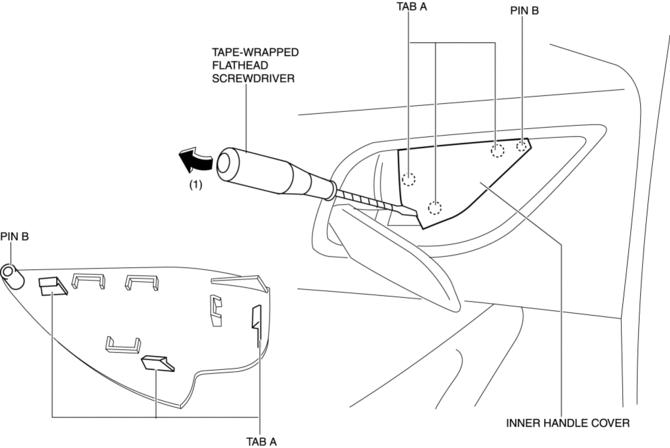
3. Insert a tape-wrapped flathead screwdriver in the position indicated by the arrow (1) in the figure and remove the inner handle cover while detach tabs A, pin B.
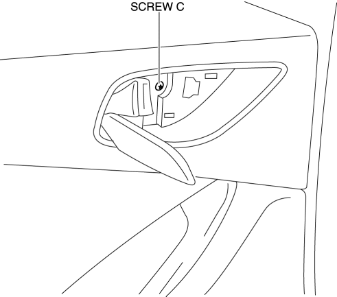
4. Remove the screw C.
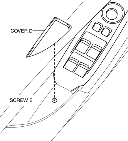
5. Remove the cover D, then remove the screw E.
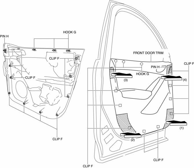
6. Take the shaded area shown in the figure, and pull the front door trim in the direction of the arrow in the order of (1), (2), (3), (4) while detaching clips F, hooks G and pin H.
CAUTION:
-
If the front door trim is removed in the same way as past vehicles by pulling it upward, it could damage clips F, hooks G and pin H. When removing the front door trim, always pull it in the direction of the arrow shown in the figure.
7. Remove the tab I in the direction of the arrow (5) shown in the figure.
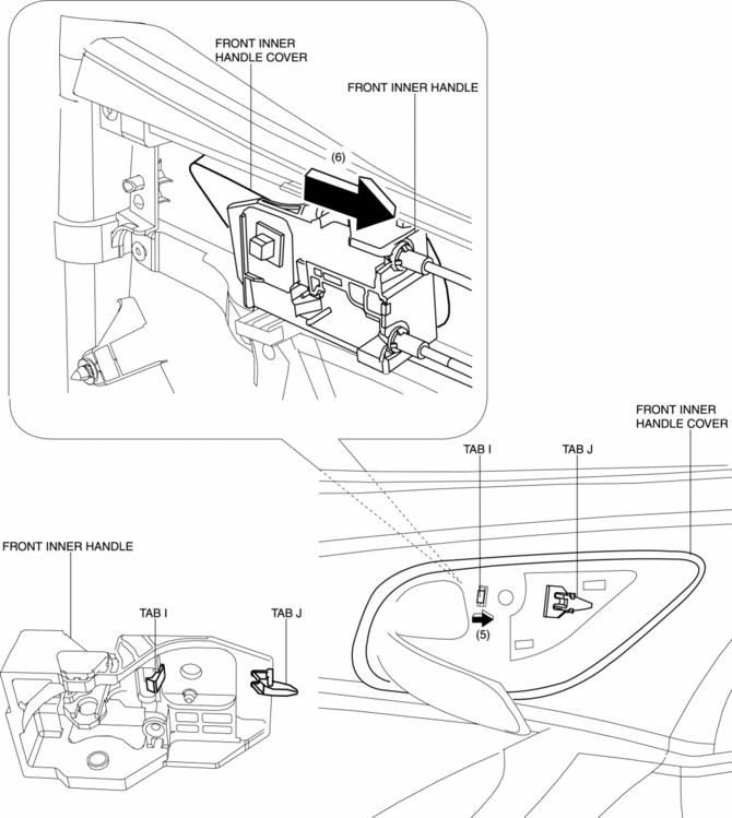
8. Remove the front inner handle in the direction of the arrow (6) shown in the figure while detaching the tab J.
9. Disconnect the power window main switch connector (driver-side) or power window subswitch connector (passenger-side).
10. Install in the reverse order of removal.
 Front Door Trim Disassembly/Assembly
Driver-side
1. Disassemble in the order shown in the figure.
1
Switch panel cover
2
Power window main switch
(See Power Window Main Switch ...
 Front Sash Molding Installation
WARNING:
Using a utility knife with bare hands can cause injury. Always wear gloves
when using a utility knife.
NOTE:
Double-sided adhesive tape has already been attached to t ...
Other materials:
Powertrain System [C66 M R]
Purpose, Function
The powertrain mechanism changes the gear combination by engaging or releasing
the clutch hub and gear, and changes the power transmission route. Because of
the change in the power transmission route, the drive force (speed, torque,
rotation direction) input from th ...
Replace Electrical Battery
If the buttons on the transmitter are inoperable and the operation indicator
light does not flash, the battery may be dead.
Replace with a new battery before the transmitter becomes unusable.
CAUTION
● Make sure the battery is installed correctly.
Battery leakage could occur if it is no ...
Differential [C66 M R]
Purpose, Function
The differential absorbs the rotation speed of the inside and outside wheel
of a wheel set when the vehicle is cornering.
Construction
Operation
Driving in a straight line
Cornering
...
