Mazda CX-5 Service & Repair Manual: Front Combination Light Disassembly/Assembly
1. Disassemble in the order shown in the figure.
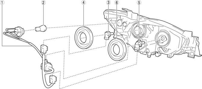
Halogen type
|
1 |
Short cord (See Short Cord Removal Note.) |
|
2 |
Parking/Front turn light bulb (See PARKING/FRONT TURN LIGHT BULB REMOVAL/INSTALLATION.) |
|
3 |
Headlight LO bulb (See HEADLIGHT BULB REMOVAL/INSTALLATION.) |
|
4 |
Cover No.1 (See Cover Installation Note.) |
|
5 |
Headlight HI bulb (DRL (Daytime running light) bulb) (See HEADLIGHT BULB REMOVAL/INSTALLATION.) |
|
6 |
Cover No.2 (See Cover Installation Note.) |
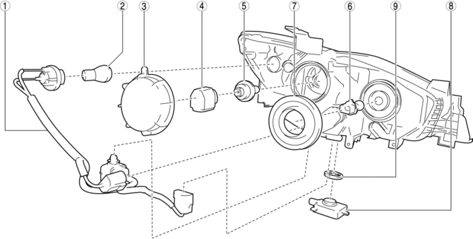
Discharge type
|
1 |
Short cord (See Short Cord Removal Note.) |
|
2 |
Parking/Front turn light bulb (See PARKING/FRONT TURN LIGHT BULB REMOVAL/INSTALLATION.) |
|
3 |
Cover No.1 (See Cover Installation Note.) |
|
4 |
Igniter (See IGNITER REMOVAL/INSTALLATION.) |
|
5 |
Headlight HI/LO bulb (See HEADLIGHT BULB REMOVAL/INSTALLATION.) |
|
6 |
DRL (Daytime running light) bulb (See DRL (DAYTIME RUNNING LIGHT) BULB REMOVAL/INSTALLATION.) |
|
7 |
Cover No.2 (See Cover Installation Note.) |
|
8 |
Discharge headlight control module (See DISCHARGE HEADLIGHT CONTROL MODULE REMOVAL/INSTALLATION.) |
|
9 |
Seal |
2. Assemble in the reverse order of disassembly.
Short Cord Removal Note
1. While pressing the clip tab in the direction of the arrows (1) shown in the figure, press the clip in the direction of the arrow (2) shown in the figure to detach the clip tab and front combination light.
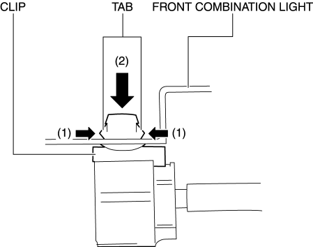
2. Remove the short cord.
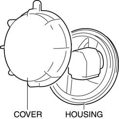
Cover Installation Note
1. Install the cover to the housing so that there is no clearance between the housing and the cover.
CAUTION:
-
If there is a gap between the housing and the cover, water may penetrate from the gap causing a malfunction in the front combination light. Verify that there is no gap between the cover and the housing.
 Front Combination Light
Purpose
Parts related to the front exterior lights are grouped and housed together
such as the headlight, front turn/parking light, headlight leveling actuator,
wiring harnesses, and conn ...
 Front Combination Light Removal/Installation
WARNING:
Incorrect servicing of the discharge headlights could result in electrical
shock. Before servicing the discharge headlights, always refer to the service
warnings..
NOTE:
...
Other materials:
Steering Gear And Linkage
Purpose/ Function
The rotational movement input from the intermediate shaft is converted to
a linear movement in the horizontal direction of the steering rack by the rack
and pinion mechanism, and then transmitted to the tires and wheels.
Construction
A size and weight-redu ...
Rear Door Glass Removal/Installation
1. Fully lower the rear door glass.
2. Disconnect the negative battery cable..
3. Remove the following parts:
a. Rear door trim.
b. Rear door quarter glass.
c. Rear door speaker.
d. Rear power window motor.
4. Press the center of the service hole cover in the direction of arrow (1) sho ...
Camshaft Position (CMP) Sensor
Purpose/Function
Detects the camshaft speed as basic information for mainly determining the
fuel injection timing and ignition timing.
Detects the camshaft speed and inputs it to the PCM as a CMP signal.
Construction
Intake CMP sensor
Installed on the cylinder head.
...
