Mazda CX-5 Service & Repair Manual: Front Bumper Reinforcement Removal/Installation
1. Disconnect the negative battery cable..
2. Remove the following parts:
a. Seal board upper.
b. Front bumper.
c. Front combination light.
d. Set plate.
e. Energy-absorbing form.
f. Front under cover No.1.
g. Bumper stiffener lower.
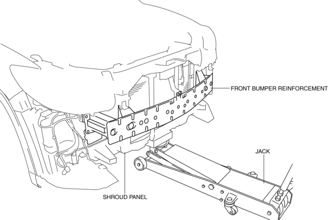
3. Support the shroud panel using a jack.
CAUTION:
-
Because the shroud panel is installed to the bumper reinforcement, support the shroud panel using a jack before removing the bumper reinforcement so as not to apply excessive force to the shroud panel.

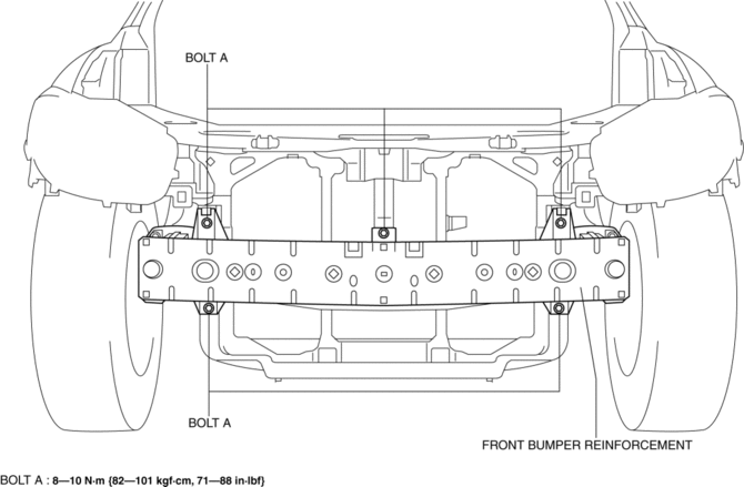
4. Remove bolts A.

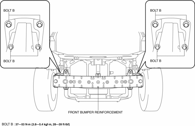
5. Remove bolts B.
CAUTION:
-
Removing the front bumper reinforcement without supporting it could cause the front bumper reinforcement to fall and cause serious injury. Always perform the procedure with at least another person to prevent the front bumper reinforcement from falling.

6. Remove the front bumper reinforcement.
7. Install in the reverse order of removal.
8. Adjust the headlight aiming..
 Front Bumper Disassembly/Assembly
1. Disassemble in the order indicated in the table.
1
Rivet
2
Grille bracket
3
Front bumper retainer
...
 Front Bumper Removal/Installation
CAUTION:
Affix the protective tape to the position (vehicle body side) shown in the
figure to prevent scratches and damage.
1. Disconnect the negative battery cable..
2. Remov ...
Other materials:
Rear Body Control Module (Rbcm) Removal/Installation
CAUTION:
If configuration is not performed when the rear body control module (RBCM)
is replaced with a new one, the vehicle specification information is not stored
in the rear body control module (RBCM) and the system will not operate normally.
When performing configuration, it ...
Sunvisors
When you need a sunvisor, lower it for use in front or swing it to the side.
Side Extension Sunvisors
The visor extender extends the sunvisor's range of sun shading.
To use, pull it out.
CAUTION
When moving the sunvisor, retract the visor extender to its original position.
Otherwise, ...
Knee Bolster Removal/Installation
1. Disconnect the negative battery cable..
2. Remove the following parts:
a. Driver-side front scuff plate.
b. Driver-side front side trim.
c. Switch panel.
d. Decoration panel.
e. Shift lever knob (MTX).
f. Front console box.
g. Shift panel.
h. Upper panel.
i. Rear console.
j. ...
