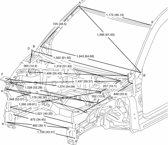
Mazda CX-5 Service & Repair Manual: Front Body Straight Line Dimensions (2) [Dimensions]
|
Point symbol |
Designation |
Hole diameter or bolt or nut size mm {in} |
|
A |
Roof seamless location |
- |
|
B |
Cabin side outer frame (front pillar outer) projection location |
- |
|
C |
Wiper bracket datum hole |
?7 {0.3} |
|
D |
Hood hinge installation hole |
?10 {0.39} |
|
E |
Front suspension upper mounting installation hole |
?10.2 {0.402} |
|
F |
Front fender panel installation hole |
?7 {0.3} |
|
G |
Apron reinforcement lower datum hole |
?10 {0.39} |
|
H |
Front fender panel installation hole |
?7 {0.3} |
|
I |
Side stay datum hole |
?10 {0.39} |
|
J |
Front bumper reinforcement installation hole |
?12 {0.47} |
|
K |
Front bumper reinforcement installation hole |
?12 {0.47} |
 Front Body Straight Line Dimensions (1) [Dimensions]
Point symbol
Designation
Hole diameter or bolt or nut size mm {in}
A
Cowl panel installation hole
?5 {0.2}
...
 Front Crossmember Removal/Installation
CAUTION:
Performing the following procedures without first removing the front ABS
wheel-speed sensor may possibly cause an open circuit in the wiring harness
if it is pulled by mistake. ...
Other materials:
Rear Seat Back Striker Removal/Installation
1. Disconnect the negative battery cable..
2. Press the push knob to fold the rear seat back.
3. Remove the following parts:
a. Trunk board.
b. Trunk end trim.
c. Rear scuff plate.
d. Trunk side trim.
4. Remove the bolts.
5. Remove the rear seat back striker.
6. Install in the ...
Engine Oil Pressure Warning Light
Purpose
The engine oil pressure warning light warns the driver that the engine oil
level is insufficient.
Function
When the instrument cluster receives the engine oil pressure warning light
request signal sent from the PCM via the CAN signal, it illuminates the engine
oi ...
M Position Switch Inspection [Fw6 A EL, Fw6 Ax EL]
Continuity Inspection
NOTE:
The M position switch is built into the selector lever component.
1. Disconnect the negative battery cable..
2. Remove the front console..
3. Disconnect the selector lever component connector.
4. Verify that the continuity between selector lever c ...
