Mazda CX-5 Service & Repair Manual: Front ABS Wheel Speed Sensor Inspection
Sensor Output Value Inspection
CAUTION:
-
Resistance inspection using other testers may cause damage to the ABS wheel-speed sensor internal circuit. Be sure to use the M-MDS to inspect the ABS wheel-speed sensor.
1. Switch the ignition to off.
2. Connect the M-MDS to the DLC-2.
3. Select the following PIDs using the M-MDS:
-
WSPD_SEN_LF (LF wheel-speed sensor)
-
WSPD_SEN_RF (RF wheel-speed sensor)
4. Start the engine and drive the vehicle.
5. Verify that the display of the M-MDS shows the same value as the speedometer.
-
If there is any malfunction, replace the ABS wheel-speed sensor.
Installation Visual Inspection
1. Inspect for the following:
-
If there is any malfunction, replace the part.
a. Excessive play of the ABS wheel-speed sensor
b. Deformation of the ABS wheel-speed sensor
c. Deformation or damage of the ABS sensor rotor
Clearance Inspection
Preparation prior to inspection
1. Remove the ABS wheel-speed sensor..
2. Remove the wheel hub and steering knuckle as a single unit..
3. Install the ABS wheel-speed sensor to the removed wheel hub, steering knuckle component, and tighten to the specified torque.
-
Tightening torque
-
8—10 N·m {82—101 kgf·cm, 71—88 in·lbf}
Clearance Inspection
1. Measure the gap between the ABS sensor rotor and ABS wheel-speed sensor using a feeler gauge.
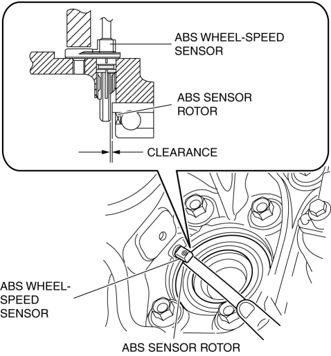
-
If not within the specification, verify the following items and repair or replace if necessary.
-
Is there deformation or damage to the ABS sensor rotor?
-
Is there deformation or damage to the ABS wheel speed sensor?
-
Is there foreign material adhering?
-
Clearance
-
0.87—1.53 mm {0.035—0.060 in}
Servicing after inspection
1. Remove the ABS wheel-speed sensor from the wheel hub, steering knuckle component.
2. Install the wheel hub, steering knuckle component..
3. Install the ABS wheel-speed sensor..
4. Inspect the front wheel alignment..
 ABS Wheel Speed Sensor And ABS Sensor Rotor
Purpose/Function
The ABS wheel-speed sensor and ABS sensor rotor detect the rotation condition
of each wheel and transmit this information to the DSC HU/CM.
The signal from the ABS w ...
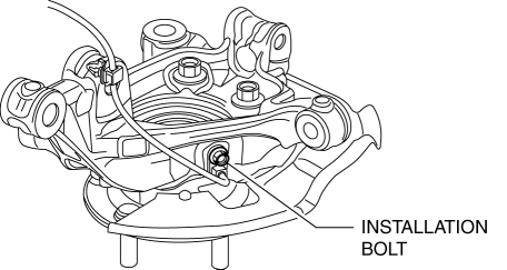
 Front ABS Wheel Speed Sensor Removal/Installation
1. Remove the mudguard..
2. Remove in the order indicated in the table.
3. Install in the reverse order of removal.
4. After installation, verify that there is no twisting in the front ABS wheel ...
Other materials:
Generator Inspection [Skyactiv G 2.0]
CAUTION:
Do not apply direct battery positive voltage to generator terminal D, otherwise
it could cause damage to the internal parts (power transistor) of the generator.
Charging system warning Light
1. Verify that the battery is fully charged.
2. Verify that the assembly conditi ...
Keyless Antenna [Keyless Entry System]
Purpose
Outputs a request signal and specifies the remote transmitter location.
Function
The keyless antennas output request signals based on the signals from the
start stop unit.
Construction, Operation
Request signals are output by the keyless antenna installed ...
High Pressure Fuel Pump Removal/Installation
WARNING:
Fuel is very flammable liquid. If fuel spills or leaks from the pressurized
fuel system, it will cause serious injury or death and facility breakage. Fuel
can also irritate skin and eyes. To prevent this, always complete the “Fuel
Line Safety Procedure”, while referring ...
