Mazda CX-5 Service & Repair Manual: Floor Insulator Removal/Installation
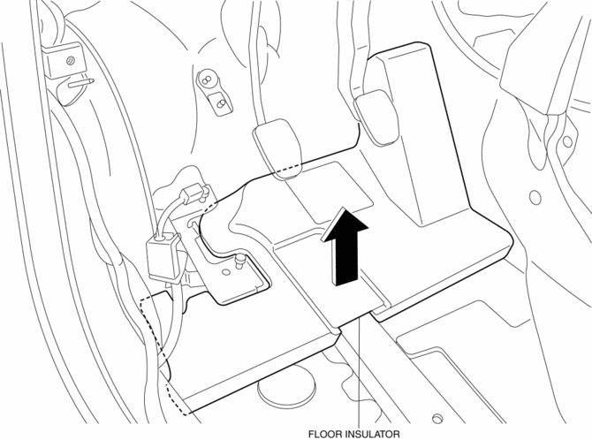
Driver-side
1. Disconnect the negative battery cable..
2. Remove the following parts:
a. Driver-side front scuff plate.
b. Driver-side front side trim.
c. Decoration panel.
d. Shift lever knob (MTX).
e. Front console box.
f. Shift panel.
g. Upper panel.
h. Rear console.
i. Side wall.
j. Front console.
k. Accelerator pedal.
3. Pull the floor insulator in the direction of the arrow and remove it.

4. Install in the reverse order of removal.
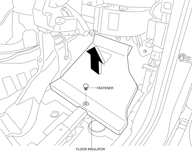
Passenger-side
1. Disconnect the negative battery cable..
2. Remove the following parts:
a. Passenger-side front scuff plate.
b. Passenger-side front side trim.
c. Grove compartment.
d. Decoration panel.
e. Shift lever knob (MTX).
f. Front console box.
g. Shift panel.
h. Upper panel.
i. Rear console.
j. Side wall.
k. Front console.
3. Remove the fastener.

4. Pull the floor insulator in the direction of the arrow and remove it.
5. Install in the reverse order of removal.
 Floor Covering Removal/Installation
1. Disconnect the negative battery cable..
2. Remove the following parts:
a. Front scuff plate.
b. Front side trim.
c. Rear scuff plate.
d. B-pillar lower trim.
e. Rear seat cushion.
f. ...
 Front Scuff Plate Removal/Installation
1. Take the shaded area shown in the figure, detach tab A while pulling the front
scuff plate in the direction of the arrow (1) shown in the figure, then detach the
hook B, clip C, and pin D while ...
Other materials:
Registering Your Vehicle in A Foreign Country (Except United States and Canada)
Registering your vehicle in a foreign country may be problematic depending on
whether it meets the specific emission and safety standards of the country in which
the vehicle will be driven. Consequently, your vehicle may require modifications
at personal expense in order to meet the regulation ...
Crankshaft Position (CKP) Sensor
Purpose/Function
Detects the crankshaft speed as basic information for mainly determining
the fuel injection timing and ignition timing.
Detects the crankshaft speed and inputs it to the PCM as a CKP signal.
Construction
Installed on the side of the cylinder block (ri ...
Front Fender Junction Installation [Panel Replacement]
Symbol Mark
Installation Procedure
1. When installing new parts, measure and adjust the body as necessary to conform
with standard dimensions.
2. Drill holes for the plug welding before installing the new parts.
3. After temporarily installing new parts, make sure the related parts fit p ...
