Mazda CX-5 Service & Repair Manual: Electric Variable Valve Timing Relay [Skyactiv G 2.0]
Purpose, Function
-
The electric variable valve timing actuator relay supplies power to the electric variable valve timing motor/driver after receiving the signal from the PCM.
Construction
-
The electric variable valve timing actuator relay is installed to the relay block..
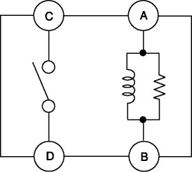
Operation
1. When current flows between A—B shown in the figure, electromagnetic power is generated, the switch between C—D is turned on, and the current flows between C—D.
2. Current flows between C—D and power is supplied to the electric variable valve timing motor/driver.
Fail-safe
-
Function not equipped.
 Corner Junction Removal [Panel Replacement]
Symbol Mark
Removal Procedure
1. Drill the 27 locations shown in the figure.
2. Remove the corner junction. ...
 Front Fender Junction Installation [Panel Replacement]
Symbol Mark
Installation Procedure
1. When installing new parts, measure and adjust the body as necessary to conform
with standard dimensions.
2. Drill holes for the plug welding before inst ...
Other materials:
Hood Latch Switch
Purpose
Detects the open/closed condition of the hood.
Function
The hood latch switch is utilized in the theft-deterrent system control.
For the theft-deterrent system, refer to (see THEFT-DETERRENT SYSTEM.).
Construction
Built into the hood latch ...
Units
Electric current
A (ampere)
Electric power
W (watt)
Electric resistance
ohm
Electric voltage
V (volt)
Length
mm (millimeter)
in (inch)
...
Air Intake Actuator Inspection [Full Auto Air Conditioner]
1. Connect battery positive voltage to air intake actuator terminal B (or C),
connect terminal C (or B) to ground, and then verify that the air intake actuator
operates as shown in the table.
If the operation condition is not normal, replace the air intake actuator.
...
