
Mazda CX-5 Service & Repair Manual: D Pillar Trim Removal/Installation
1. Disconnect the negative battery cable..
2. Remove the following parts:
a. Trunk board.
b. Trunk end trim.
c. Rear scuff plate.
d. Trunk side trim.
3. Take the shaded area shown in the figure, and remove the D-pillar trim in the direction of the arrow in the order of (1), (2), (3) while detaching clips A, pins B.
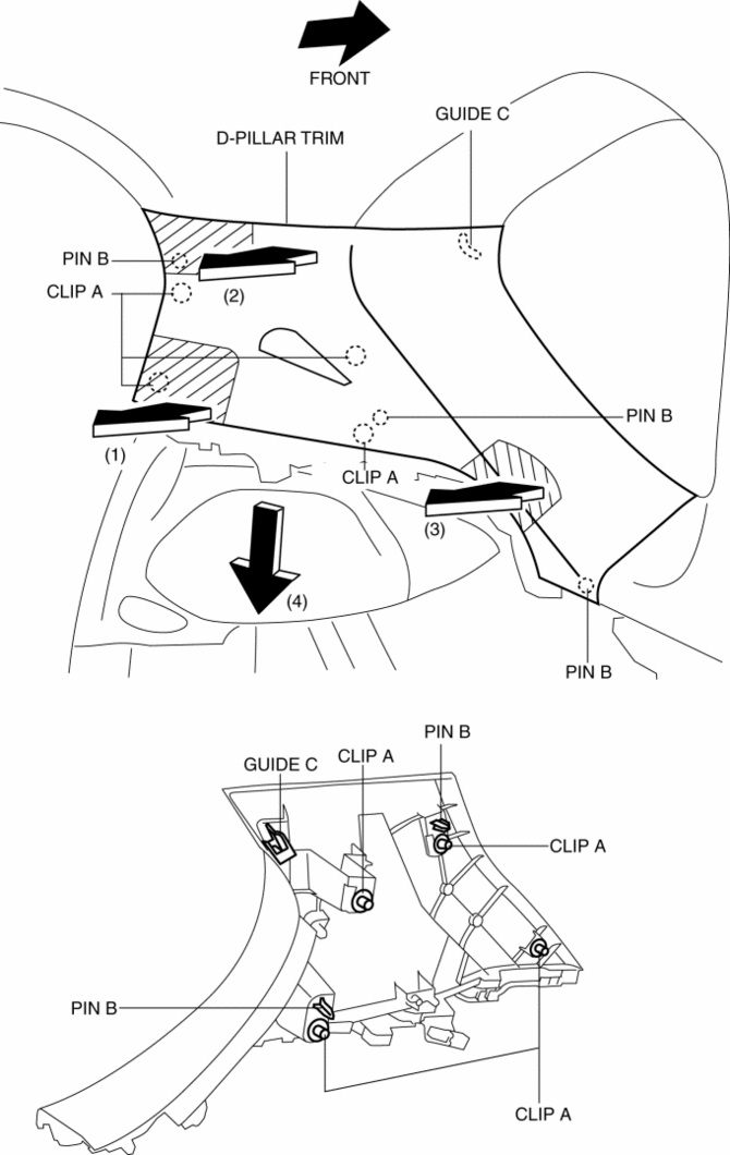
4. Pull the D-pillar trim in the direction of the arrow (4) and remove the D-pillar trim while detaching the guide C.
5. Install in the reverse order of removal.
 Column Cover Removal/Installation
1. Pull down the steering wheel.
2. Press the shaded area shown in the figure using your thumb, and lift the upper
column cover in the direction of arrow (1).
3. Pull the upper column cover ...
 Dashboard Disassembly/Assembly
1. Disassemble in the order indicated in the table.
1
Wiring harness
2
Screw A
3
Screw B
4
...
Other materials:
Instrument Cluster Removal/Installation
CAUTION:
If configuration is not performed when the instrument cluster is replaced
with a new one, the vehicle specification information is not stored in the instrument
cluster and the system will not operate normally.
When performing configuration, it is necessary to read the ...
Evaporator Temperature Sensor [Manual Air Conditioner]
Purpose
The evaporator temperature sensor detects the airflow temperature passing
through the evaporator.
Function
The evaporator temperature sensor converts the detected temperature to an
electric signal.
Construction
A thermistor-type evaporator temperature s ...
Hydraulic Variable Valve Timing Actuator
Purpose, Function
The hydraulic variable valve timing actuator operates according to the hydraulic
pressure and changes the phases of the exhaust camshaft. As a result, the open/close
period of the exhaust valve is changed, optimized valve timing in accordance
with driving conditions ...
