Mazda CX-5 Service & Repair Manual: Seat Warmer System
Purpose
-
The seat warmer system warms the front seat cushion and front seat back using the seat warmer unit.
Function
-
The seat warmer unit warms the seat cushion and seat back by supplying power to the built-in filaments.
-
The seat warmer unit can adjust the temperature between 3 levels.
-
The temperature level of the seat warmer unit changes each time the seat warmer switch is pressed.
-
The seat warmer control unit supplies power to the seat warmer unit and increases the temperature around the seat back and seat cushion up to the average temperature which is applied to the temperature level.
|
Switch display |
Temperature level |
Average temperature around seat warmer unit |
||
|
With manual air conditioner system |
With full-auto air conditioner system |
Seat cushion side |
Seat back side |
|
|
|
|
0 |
— |
|
|
|
|
1 |
Approx. 37°C
|
|
|
|
|
2 |
Approx. 40°C
|
Approx. 42°C
|
|
|
|
3 |
Approx. 42°C
|
Approx. 47°C
|


-
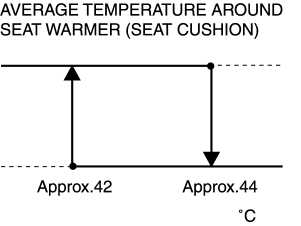
The seat warmer control unit detects the average temperature around the seat warmer unit (seat cushion side) based on a signal from thermostat (seat cushion side) to prevent overheating, cuts off the power supply to the seat warmer unit when the temperature reaches the specification, and decreases the average temperature below the specified temperature.
-
When the seat warmer control unit detects that the average temperature around the seat warmer unit (seat cushion side) decreases below the specified temperature based on a signal from the thermostat, power is supplied to the seat warmer unit again to increase the temperature up to the specified temperature.
|
Temperature level |
Average temperature around seat warmer unit (seat cushion side) |
|||
|
Cloth type |
Leather type |
|||
|
Increase start temperature |
Decrease start temperature |
Increase start temperature |
Decrease start temperature |
|
|
0 |
— |
|||
|
1 |
Approx. 23°C
|
Approx. 25°C
|
Approx. 23°C
|
Approx. 25°C
|
|
2 |
Approx. 23°C
|
Approx. 34°C
|
Approx. 30°C
|
Approx. 32°C
|
|
3 |
Approx. 42°C
|
Approx. 44°C
|
Approx. 38°C
|
Approx. 40°C
|
-
The seat warmer control unit maintains a constant average temperature around the seat warmer unit by continuing to supply power to the seat warmer unit.
Ex.) Cloth-type temperature level is 3:
Structural view
-
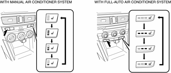
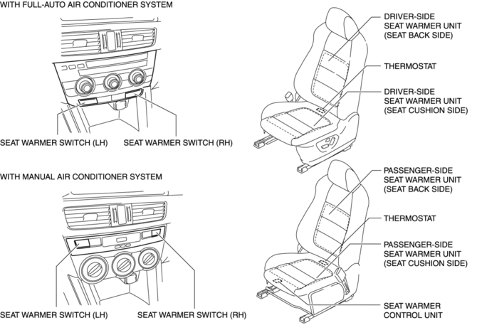
The seat warmer switch is built into the climate control unit.
-
The seat warmer unit is adhered to the front seat cushion and front seat back.
-
The seat warmer control unit is located on the bottom of the passenger-side front seat.
-
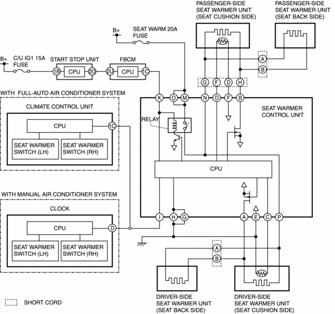
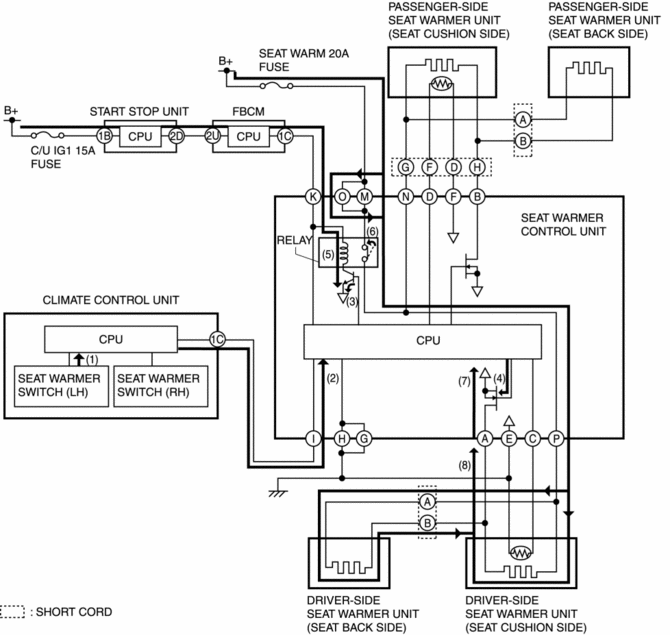
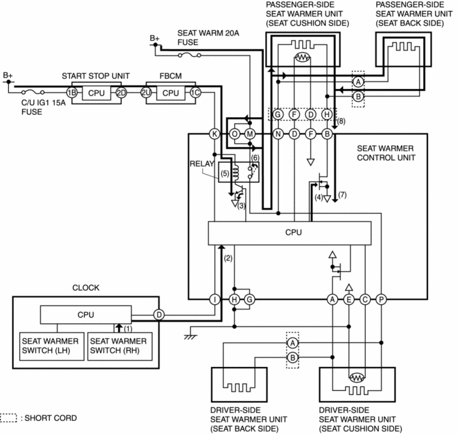
System wiring diagram
Operation
Ex.) Seat warmer temperature level on cloth-type driver's side is set at 3 (with full-auto air conditioner system):
1. The climate control unit determines (1) the average increase temperature of the seat warmer unit by operating the seat warmer switch (driver-side).
2. The climate control unit sends (2) the temperature level "3" signal for the seat warmer unit to the CPU of the seat warmer control unit.
3. When the CPU of the seat warmer control unit receives the operation level "3" signal from the climate control unit, it supplies the base current to the transistor built into the seat warmer control unit (3), and the gate voltage is applied to the FET simultaneously (4).
4. If the base current is supplied, the transistor supplies collector current to the relay coil (5).
5. If collector current is supplied, the relay coil energizes and turns on the relay switch (6).
6. When the gate voltage is applied, the FET completes the circuit between seat warmer control unit terminal A and ground (7).
7. When the relay switch built into the seat warmer control unit turns on and the FET circuit is completed, the driver-side seat warmer unit circuit is completed (8) and the driver-side front seat cushion and front seat back warm.
-
When the climate control unit detects that the temperature around the seat reaches approx. 44°C
, the power supply is cut off.
Ex.) Seat warmer temperature level on cloth-type passenger-side is set at 3 (with manual air conditioner system):
1. The climate control unit determines (1) the average increase temperature of the seat warmer unit by operating the seat warmer switch (passenger-side).
2. The climate control unit sends (2) the temperature level "3" signal for the seat warmer unit to the CPU of the seat warmer control unit.
3. When the CPU of the seat warmer control unit receives the operation level "3" signal from the climate control unit, it supplies the base current to the transistor built into the seat warmer control unit (3), and the gate voltage is applied to the FET simultaneously (4).
4. If the base current is supplied, the transistor supplies collector current to the relay coil (5).
5. If collector current is supplied, the relay coil energizes and turns on the relay switch (6).
6. When the gate voltage is applied, the FET completes the circuit between seat warmer control unit terminal B and ground (7).
7. When the relay switch built into the seat warmer control unit turns on and the FET circuit is completed, the driver-side seat warmer unit circuit is completed (8) and the driver-side front seat cushion and front seat back warms.
-
When the clock detects that the temperature around the seat reaches approx. 44°C
, the power supply is cut off.
Fail-safe
-
Function not equipped.
 Seat Warmer Switch Removal/Installation
NOTE:
The seat warmer switch are integrated into the climate control unit. (with
full-auto air conditioner system)
The seat warmer switch are integrated into the clock. (with manual ...
 Seat Warmer Unit Inspection
WARNING:
Handling a side air bag improperly can accidentally operate (deploy) the
air bag, which may seriously injure you. Read the service warnings/cautions
in the Workshop Manual befor ...
Other materials:
Front Fender Panel Removal/Installation
1. Disconnect the negative battery cable..
2. Remove the following parts:
a. Front bumper.
b. Front combination light.
c. Front bumper slider.
d. Front over fender.
3. Remove bolts A and fasteners B.
4. Remove bolts C.
5. Remove the front fender panel.
6. Install in the reverse ...
Audio Unit Personalization Features Setting Procedure
Door Locks Systems
1. Switch the ignition ON (engine off or on).
2. Turn the audio unit power on.
3. Select the following from the audio unit screen.
a. “Setup”
b. “Vehicle”
c. “Door Locks“
4. Select the following items and change the setting.
Advanced keyless entry system ...
Wheel Apron Component Installation [Panel Replacement]
Symbol Mark
Installation Procedure
1. When installing new parts, measure and adjust the body as necessary to conform
with standard dimensions.
2. Drill holes for the plug welding before installing the new parts.
3. After temporarily installing new parts, make sure the related parts fit p ...
