Mazda CX-5 Service & Repair Manual: Clutch Master Cylinder Removal/Installation [C66 M R]
CAUTION:
-
Secure the steering wheel using tape or a cable to prevent the steering shaft from rotating after disconnecting the steering shaft. If the steering wheel rotates after the steering shaft and the steering gear and linkage are disconnected, the internal parts of the clock spring could be damaged.
-
Do not allow clutch fluid to get on a painted surface. Clutch fluid contains properties which can dissolve the paint. If clutch fluid gets on a painted surface, wash it off with water immediately and wipe the area off completely.
Removal
1. Disconnect the negative battery cable..
2. Remove the air cleaner component. (ex: air cleaner, air hose).
3. Remove the battery component. (ex: battery, battery tray and PCM component).
4. Remove the clutch pedal position switch..
5. Remove the starter interlock switch..
6. Remove the joint cover..
7. Disconnect the steering shaft from steering gear..
8. Disconnect the clutch pipe and hose No.1 from clutch master cylinder, and plug it to avoid clutch fluid leakage..
9. Disconnect the clutch reserve hose from clutch master cylinder, and plug it to avoid clutch fluid leakage..
10. Remove the clutch master cylinder using the following procedure:
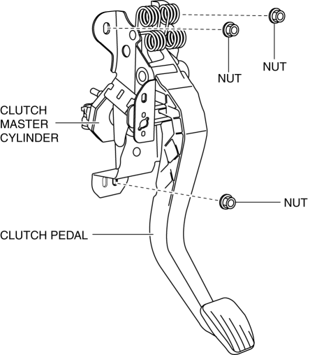
a. Remove the clutch pedal and the clutch master cylinder as a single unit.
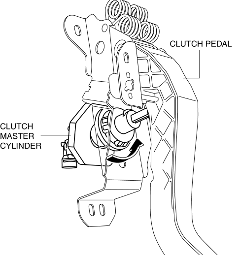
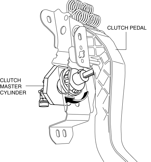
b. Rotate the clutch master cylinder in the direction of the arrow shown in the figure to disconnect the clutch master cylinder (body) and clutch pedal.
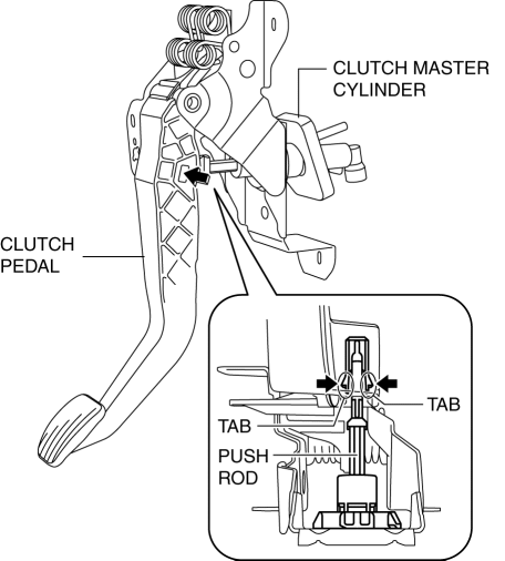
c. Disengage the tabs of the push rod and remove the master cylinder.
Installation
1. Install the clutch master cylinder using the following procedure:
a. Engage the tabs of the push rod with the clutch pedal as shown in the figure.
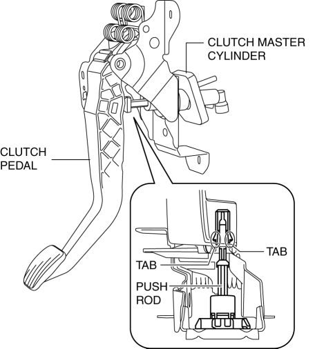
b. Rotate the clutch master cylinder in the direction shown until it stops.
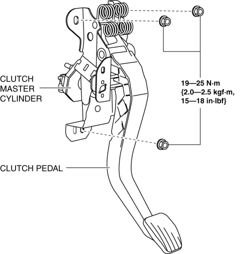
c. Install the clutch pedal and the clutch master cylinder as a single unit.
2. Connect the clutch reserve hose to clutch master cylinder..
3. Connect the clutch pipe and hose No.1 to clutch master cylinder..
4. Connect the steering shaft..
5. Install the joint cover..
6. Bleed the air from the clutch system..
7. Inspect the clutch pedal..
8. Install a new starter interlock switch..
9. Install a new clutch pedal position switch..
10. Install the battery component. (ex: battery, battery tray and PCM component).
11. Install the air cleaner component. (ex: air cleaner, air hose).
12. Connect the negative battery cable..
13. Fully depress the clutch pedal, and verify that the engine starts.
 Clutch Fluid Replacement/Air Bleeding [C66 M R]
CAUTION:
Do not allow clutch fluid to get on a painted surface. Clutch fluid contains
properties which can dissolve the paint. If clutch fluid gets on a painted surface,
wash it off with ...
 Clutch Pedal Inspection [C66 M R]
NOTE:
For the clutch pedal inspection, note the following and measure each inspection
location.
Measure the center of the upper surface of the pedal pad for each inspection.
...
Other materials:
Plastic Parts Heat Resisting Temperature [Plastic Body Parts]
Part Name
Code
Material Name
Heat resisting
Temperature°C{°F}
Windshield molding
PVC
POLYVINYLCHLORIDE
95 {203}
Cowl grille
PP
POLYPROPYLENE
...
Oil Pump [Fw6 A EL, Fw6 Ax EL]
Purpose/Function
The oil pump generates hydraulic pressure in the oil line of the automatic
transaxle together with supplying lubrication to powertrain related parts.
Construction
The oil pump has adopted a gear type with built-in outer and inner rotors.
The inner roto ...
Oil Cooler
Purpose, Function
The oil cooler routes engine oil and engine coolant through the interior
and disperses the engine oil heat using the engine coolant. As a result, the
oil temperature is maintained properly to reduce the engine oil deterioration.
Construction
A 9-layered ty ...
