Mazda CX-5 Service & Repair Manual: Clutch Pedal Inspection [C66 M R]
NOTE:
-
For the clutch pedal inspection, note the following and measure each inspection location.
-
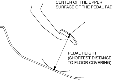
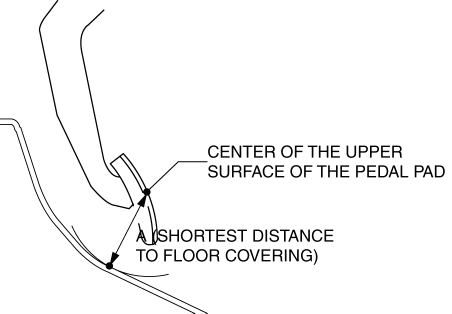
Measure the center of the upper surface of the pedal pad for each inspection.
-
If the distance from the pedal pad to the floor covering is measured, measure the shortest distance from the center of the upper surface of the pedal pad to the floor covering.
Pedal Inspection Preparation
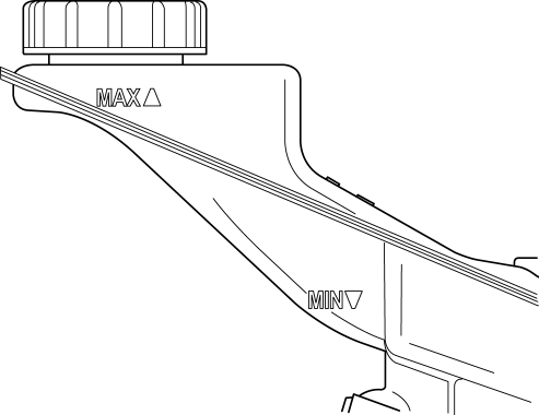
1. Verify that the clutch fluid is between the MIN mark and the MAX mark.
2. Verify that there is no clutch fluid leakage..
Pedal Height Inspection
1. Perform “Pedal Inspection Preparation”..
2. Measure the pedal height with the clutch pedal released as shown in the figure.
-
Pedal height (reference value)
-
150 mm {5.91 in} (U.S.A. and CANADA)
-
152 mm {5.98 in} (Except U.S.A. and CANADA)
-
If it is not the specification, replace the clutch pedal..
Pedal Free Play Inspection
1. Perform “Pedal Inspection Preparation”..
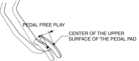
2. Depress the clutch pedal by hand until clutch resistance is felt, and measure the pedal free play as shown in the figure.
-
Pedal free play (reference value)
-
10 mm {0.39 in} or less
-
If it exceeds the specification, replace the clutch pedal..
Pedal Full Stroke Inspection
1. Perform “Pedal Inspection Preparation”..
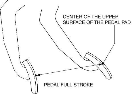
2. Depress the clutch pedal from the released condition to the full depression position, and measure the pedal full stroke as shown in the figure.
-
Pedal full stroke (reference value)
-
146 mm {5.75 in}
-
If it is not the specification, replace the clutch pedal..
Clutch Disengagement Point Inspection
WARNING:
-
When performing the following procedure, make sure that the area around the vehicle is free of people or objects as the vehicle might move suddenly.
1. Perform “Pedal Inspection Preparation”..
2. Verify that the pedal height is normal..
3. Verify that the pedal free play is normal..
4. Verify that the pedal full stroke is normal..
5. Apply the parking brake and fix the front and rear wheels with wheel chocks.
6. Start the engine.
7. With the clutch pedal depressed, move the shift lever to the position just before engaging the reverse gear. (Do not shift completely to reverse position)
8. Gradually release the clutch pedal and then hold it at the point where the sound of gear-grinding begins (clutch disengagement point).
9. Measure distance A as shown in the figure when the clutch pedal is at the clutch disengagement point.
-
Distance A (reference value)
-
82 mm {3.2 in} or more
-
If it is less than the specification, bleed the air from the clutch system..
 Clutch Master Cylinder Removal/Installation [C66 M R]
CAUTION:
Secure the steering wheel using tape or a cable to prevent the steering shaft
from rotating after disconnecting the steering shaft. If the steering wheel
rotates after the steer ...
 Clutch Pedal Position (CPP) Switch Inspection [Skyactiv G 2.0]
Continuity Inspection
1. Verify that the CPP switch is installed properly..
2. Disconnect the negative battery cable..
3. Disconnect the CPP switch connector.
4. Verify that the continuity betw ...
Other materials:
Room Light Control System
Outline
The room light control system changes the illumination condition and illumination
level of the interior lights (door position) according to whether the doors
are opened/closed and locked/unlocked.
The room light control system is controlled by the rear body control modul ...
Cruise Control System
Outline
Enables driving at a constant speed by setting the vehicle speed with the
cruise control switch instead of operating the accelerator pedal.
The PCM controls the throttle valve actuator to maintain the vehicle at a
constant speed.
Component and function
...
Engine Coolant Temperature (ECT) Sensor Removal/Installation
WARNING:
When the engine is hot, it can badly burn. Turn off the engine and wait until
it is cool before removing the ECT sensor.
ECT Sensor No.1
1. Disconnect the negative battery cable..
2. Remove the plug hole plate..
3. Drain the engine coolant..
4. Pull out the evaporati ...
