Mazda CX-5 Service & Repair Manual: Side Garnish Removal
Front
1. Insert a tape-wrapped flathead screwdriver in the position shown in the figure, move it in the direction of the arrow (1) to remove the clip A.
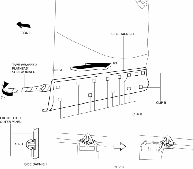
2. Slide the side garnish in the direction of the arrow (2) shown in the figure and remove clips B from side garnish.
3. Remove clips B from the body.
4. When reusing the side garnish, install clip A and B to the body.
Rear
1. Insert a tape-wrapped flathead screwdriver in the position shown in the figure, move it in the direction of the arrow (1) to remove the clip A.
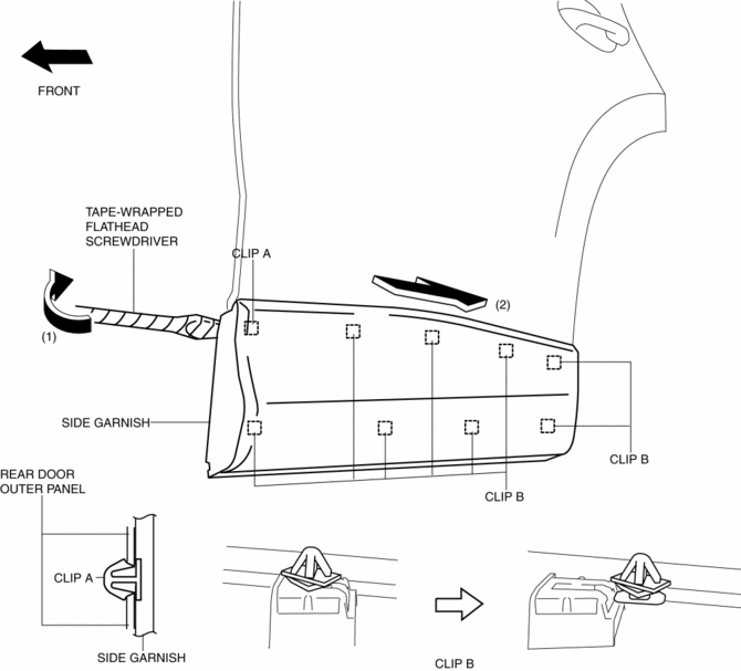
2. Slide the side garnish in the direction of the arrow (2) shown in the figure and remove clips B from side garnish.
3. Install clips B to the body.
4. When reusing the side garnish, install clip A and B to the body.
 Side Garnish Installation
1. Install clip A.
Front
Rear
2. Install clip B to the vehicle from the front side. ...
 Side Sill Panel Installation [Panel Replacement]
Symbol Mark
Installation Procedure
Side sill (front side)
1. When installing new parts, measure and adjust the body as necessary to conform
with standard dimensions.
2. Drill holes for the ...
Other materials:
Rear Differential Disassembly
WARNING:
The engine stand is equipped with a self-lock mechanism, however, if the
rear differential is in a tilted condition, the self-lock mechanism could become
inoperative. If the rear differential unexpectedly rotates it could cause injury,
therefore do not maintain the rear dif ...
Rear Window Defroster/Outer Mirror Heater
Outline
Fogging is cleared from the rear window and outer mirror glass by heating
of the filament.
Structural view
System wiring diagram
Vehicles with full-auto air conditioner system
Vehicles with manual air conditioner system
Construction
Rear window defroster
...
Synchronizer Mechanism [C66 M R]
Purpose, Function
For smooth gear changes, the synchronizer mechanism synchronizes the rotation
of the engaging area and engages gears.
Construction
Detent ball-type synchronizer key
A detent ball-type synchronizer key has been adopted for the synchronizer
mechanism ex ...
