Mazda CX-5 Service & Repair Manual: Oil Seal (Differential) Replacement [Fw6 A EL, Fw6 Ax EL]
Transaxle Case Side
1. Remove the front under cover No.2..
2. Drain the ATF..
3. Disconnect the drive shaft (LH) from the transaxle..
CAUTION:
-
The oil seal is easily damaged by the sharp edges of the drive shaft splines. Do not let the splines contact the oil seal.
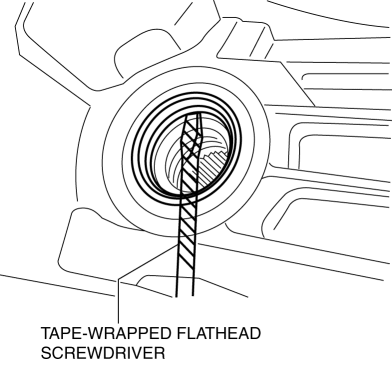
4. Remove the oil seal using a tape-wrapped flathead screwdriver.
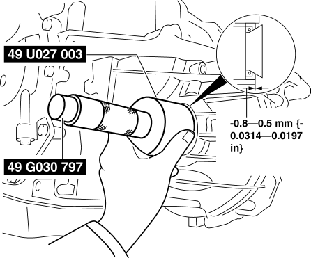
5. Using the SSTs
and a hammer, tap a new oil seal in evenly until the SST
(49 U027 003) contacts the transaxle case.
6. Coat the lip of the oil seal with ATF.
7. Install the drive shaft (LH) to the transaxle..
8. Add the ATF..
9. Install the front under cover No.2..
10. Perform the “Mechanical System Test”..
Converter housing Side (FW6A-EL)
1. Remove the front under cover No.2..
2. Drain the ATF..
3. Disconnect the drive shaft (RH)..
CAUTION:
-
The oil seal is easily damaged by the sharp edges of the drive shaft splines. Do not let the splines contact the oil seal.
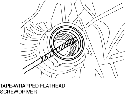
4. Remove the oil seal using a tape-wrapped flathead screwdriver.
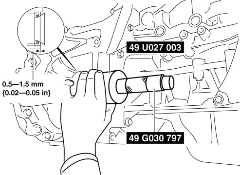
5. Using the SSTs
and a hammer, tap a new oil seal in evenly until the SST
(49 U027 003) contacts the transaxle case.

6. Coat the lip of the oil seal with ATF.
7. Install the drive shaft (RH)..
8. Add the ATF..
9. Install the front under cover No.2..
10. Perform the “Mechanical System Test”..
Converter housing Side (FW6AX-EL)
1. Remove the front under cover No.2..
2. Drain the ATF..
3. Remove the transfer..
CAUTION:
-
The oil seal is easily damaged by the sharp edges of the drive shaft splines. Do not let the splines contact the oil seal.
4. Remove the oil seal using a tape-wrapped flathead screwdriver.
5. Using the SSTs
and a hammer, tap a new oil seal in evenly until the SST
(49 U027 003) contacts the transaxle case.
6. Coat the lip of the oil seal with ATF.
7. Install the transfer..
8. Add the ATF..
9. Install the front under cover No.2..
10. Perform the “Mechanical System Test”..
 Oil Seal (Differential) Replacement [C66 M R]
1. Remove the front under cover No.2..
2. Drain the manual transaxle oil..
3. Disconnect the drive shaft (LH) from the MTX..
4. Disconnect the drive shaft (RH) from the MTX..
5. Remove the oil ...
 Rear Differential
Purpose, Function
A rear differential with an integrated coupling component has been adopted,
reducing size and weight.
An aluminum differential carrier has been adopted, reducing we ...
Other materials:
Scheduled Maintenance (U.S.A., Canada, and Puerto Rico)
Follow Schedule 1 if the vehicle is operated mainly where none of the following
conditions apply.
• Repeated short-distance driving
• Driving in dusty conditions
• Driving with extended use of brakes
• Driving in areas where salt or other corrosive
materials are used
• Driving on ...
Fuel Gauge Sender Unit Inspection [2 Wd]
NOTE:
For the fuel gauge sender unit removal/installation, refer to the fuel pump
removal/installation because the fuel gauge sender unit is integrated with the
fuel pump..
1. Verify that the resistance at fuel gauge sender unit terminals D and C is
as indicated in the table ac ...
Auto Dimming Mirror
Purpose
The automatic glare prevention rearview mirror prevents the driver from being
affected by light from vehicles at the rear.
Structural view
System wiring diagram
Function
The automatic glare prevention rearview mirror detects the level of the surrounding
li ...
