Mazda CX-5 Service & Repair Manual: Seat Warmer Unit Inspection
WARNING:
-
Handling a side air bag improperly can accidentally operate (deploy) the air bag, which may seriously injure you. Read the service warnings/cautions in the Workshop Manual before handling the front seat (side air bag integrated)..
CAUTION:
-
If the slide bar is operated after the front seat is removed, the left/right slide positions will deviate and the adjuster unit could be damaged after the front seat is installed. After removing a front seat, do not operate the slider lever.
-
Verify that there are no malfunctions in the forward/back slide of the seat and in the adjuster unit after installing a front seat.
-
When performing the procedure with a front seat removed from the vehicle, perform the procedure on a clean cloth so as not to damage or soil the seat.
-
When the passenger's seat is removed, perform the seat weight sensor inspection using the M-MDS after installing the passenger's seat..
-
When the passenger's seat is replaced with a new one, perform the seat weight sensor calibration using the M-MDS..
Driver-Side
Seat cushion side
1. Switch the ignition to off.
2. Disconnect the negative battery cable and wait 1 min. or more
..
3. Remove the front seat..
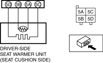
4. Inspect for continuity between the seat warmer unit connector terminal 5C—5D.


-
If not as specified, replace the front seat cushion pad..
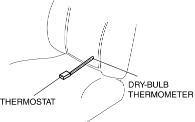
5. Measure the temperature around the thermostat.

NOTE:
-
To make the temperature around the thermostat at the normal temperature, the seat warmer is left for 30 minutes or more while turned off.
6. Measure the resistance between the seat warmer unit connector terminal 5A—5B, records with the surrounding temperature of the thermostat measured beforehand.
7. Connect the negative battery cable.
8. Connect the seat warmer unit connector.
9. Switch the seat warmer switch to Lo position, and warm the seat warmer.
10. Measure the resistance between the seat warmer unit connector terminal 5A—5B, and report it.
11. Switch the seat warmer switch to High position, and warm the seat warmer.
12. Measure the resistance between the seat warmer unit connector terminal 5A—5B, it is confirmed that there is a change from the resistance recorded beforehand.
-
If the change in resistance cannot be confirmed, replace the front seat cushion pad..
Seat back side
1. Switch the ignition to off.
2. Disconnect the negative battery cable and wait 1 min. or more
..
3. Remove the front seat..
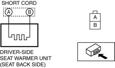
4. Inspect for continuity between the seat warmer unit connector (short code) terminal A—B.

-
If not as specified, replace the front seat back pad..

Passenger-Side
Seat cushion side
1. Switch the ignition to off.
2. Disconnect the negative battery cable and wait 1 min. or more
..
3. Remove the front seat..
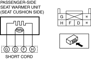
4. Inspect for continuity between the seat warmer unit connector (short code) terminal G—H.


-
If not as specified, replace the front seat cushion pad..
5. Measure the temperature around the thermostat.

NOTE:
-
To make the temperature around the thermostat at the normal temperature, the seat warmer is left for 30 minutes or more while turned off.
6. Measure the resistance between the seat warmer unit connector terminal D—F, records with the surrounding temperature of the thermostat measured beforehand.
7. Connect the negative battery cable.
8. Connect the seat warmer unit connector.
9. Switch the seat warmer switch to Lo position, and warm the seat warmer.
10. Measure the resistance between the seat warmer unit connector terminal D—F, and report it.
11. Switch the seat warmer switch to High position, and warm the seat warmer.
12. Measure the resistance between the seat warmer unit connector terminal D—F, it is confirmed that there is a change from the resistance recorded beforehand.
-
If the change in resistance cannot be confirmed, replace the front seat cushion pad..
Seat back side
1. Switch the ignition to off.
2. Disconnect the negative battery cable and wait 1 min. or more
..
3. Remove the front seat..
4. Inspect for continuity between the seat warmer unit connector (short code) terminal A—B.

-
If not as specified, replace the front seat back pad..

 Seat Warmer System
Purpose
The seat warmer system warms the front seat cushion and front seat back using
the seat warmer unit.
Function
The seat warmer unit warms the seat cushion and seat back by ...
 Seat Weight Sensor Calibration [Two Step Deployment Control System]
CAUTION:
If any of the following work is performed, perform the seat weight sensor
calibration using the M-MDS.
Replacement with a new seat weight sensor
Replacement ...
Other materials:
Awd Solenoid Inspection
1. Disconnect the negative battery cable.
2. Disconnect the AWD solenoid connector.
3. Measure resistance between AWD solenoid connector terminals A and B.
If the resistance is not within the specification, replace the coupling unit.
AWD solenoid resistance
2.2—2.7 oh ...
Front Frame (Rear) Installation [Panel Replacement]
Symbol Mark
Installation Procedure
1. When installing new parts, measure and adjust the body as necessary to conform
with standard dimensions.
2. Drill holes for the plug welding before installing the new parts.
3. After temporarily installing new parts, make sure the related parts fit p ...
Seat
Outline
Front seat
A manual seat or power seat has been adopted on the driver's seat.
A seat warmer system has been adopted on the front seats. (with seat warmer
system)
A manual seat has been adopted on the front passenger's seat.
A side air bag module is ...
