Mazda CX-5 Service & Repair Manual: Seat Track Position Sensor Removal/Installation [Two Step Deployment Control System]
1. Switch the ignition to off.
2. Disconnect the negative battery cable and wait for 1min or more
..
3. Remove the front driver’s seat..
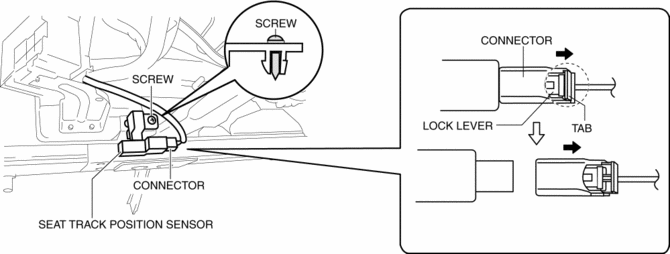
4. Disconnect the connector from the seat track position sensor by pressing the connector tab and pulling out the lock lever in the direction of the arrow.
-
When connecting the seat track position sensor connector, insert the lock lever (connector disconnection prevention lever) completely.

5. Remove the screw.
6. Detach the tab while lifting up the seat track position sensor in the direction of the arrow (1).

7. Rotate the seat track position sensor in the direction of the arrow (2).
8. Rotate the seat track position sensor in the direction of the arrow (3).
9. Remove the seat track position sensor (4).
10. Install in the reverse order of removal.
11. Switch the ignition ON (engine off or on).
12. Verify that the air bag system warning light illuminates for approx. 6 s
and goes out.
-
If the air bag system warning light does not operate normally, refer to the on-board diagnostic system (air bag system) and perform inspection of the system..
 Seat
Seat
Outline
Front seat
A manual seat or power seat has been adopted on the driver's seat.
A seat warmer system has been adopted on the front seats. (with seat warmer
system)
...
 Seat Track Position Sensor [Two Step Deployment Control System]
Purpose
The seat track position sensor detects the front and back positions of the
driver seat.
Function
The seat track position sensor converts the seat position into an electr ...
Other materials:
Igniter Removal/Installation
WARNING:
Incorrect servicing of the discharge headlights could result in electrical
shock. Before servicing the discharge headlights, always refer to the service
warnings..
Igniter (LH)
1. Disconnect the negative battery cable..
2. Remove the air cleaner cover..
3. Remove th ...
Charging System Warning Light
Purpose, Function
Warns the driver of a charging system malfunction.
Construction
The charging system warning light is built into the instrument cluster..
Operation
Illuminates when a malfunction occurs in the charging system and DTCs is
stored in the PCM.
...
Shroud Side Member Removal [Panel Replacement]
Symbol Mark
Removal Procedure
1. Drill the 3 locations indicated by (A) shown in the figure.
2. Drill the 8 locations indicated by (B) and 2 locations indicated by (C) shown
in the figure.
NOTE:
When drilling the 3 locations indicated by (A) and 2 locations indicated
by (C) sh ...
