Mazda CX-5 Service & Repair Manual: Igniter Removal/Installation
WARNING:
-
Incorrect servicing of the discharge headlights could result in electrical shock. Before servicing the discharge headlights, always refer to the service warnings..
Igniter (LH)
1. Disconnect the negative battery cable..
2. Remove the air cleaner cover..
3. Remove the relay and fuse block upper cover..
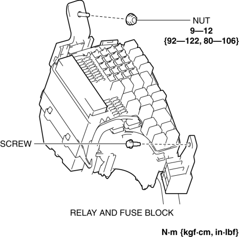
4. Remove the nut and screw.
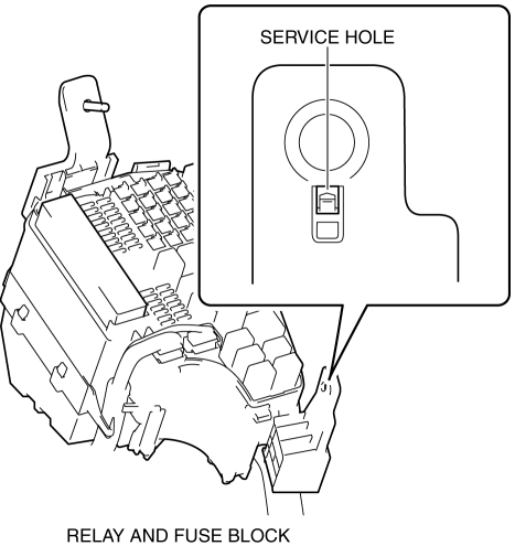
5. Insert a tape-wrapped flathead screwdriver into the service hole in the position shown in the figure.
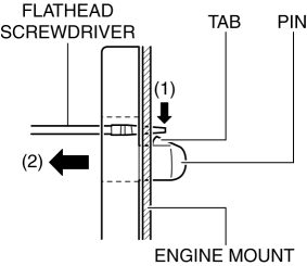
6. While pressing the pin tab in the direction of the arrow (1) shown in the figure using a flathead screwdriver, pull the pin in the direction of the arrow (2) shown in the figure to detach the pin tab and engine mount.
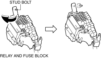
7. Pull out the relay and fuse block from the stud bolt and set it aside as shown in the figure.
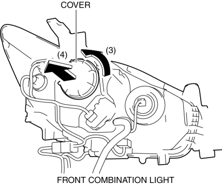
8. Rotate the cover in the direction of the arrow (3) shown in the figure and remove it from the front combination light in the direction of the arrow (4) shown in the figure.
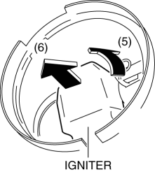
9. Rotate the igniter in the direction of the arrow (5) shown in the figure and remove it from the front combination light in the direction of the arrow (6) shown in the figure.
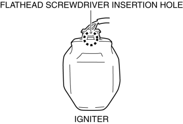
10. Insert the flathead screwdriver into the gap between the igniter and connector shown in the figure.
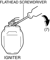
11. Move the flathead screwdriver in the direction of the arrow (7) shown in the figure, lift up the connector, and disconnect it.
12. Install in the reverse order of removal.
Igniter (RH)
1. Disconnect the negative battery cable..
2. Remove the washer tank bracket..
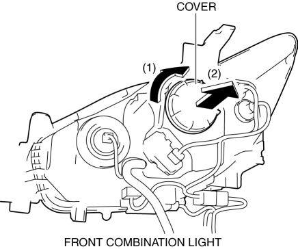
3. Rotate the cover in the direction of the arrow (1) shown in the figure and remove it from the front combination light in the direction of the arrow (2) shown in the figure.
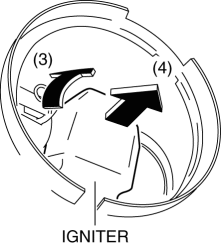
4. Rotate the igniter in the direction of the arrow (3) shown in the figure and remove it from the front combination light in the direction of the arrow (4) shown in the figure.
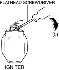
5. Insert the flathead screwdriver into the gap between the igniter and connector shown in the figure.

6. Move the flathead screwdriver in the direction of the arrow (5) shown in the figure, lift up the connector, and disconnect it.
7. Install in the reverse order of removal.
 Fuel Distributor [Skyactiv G 2.0]
Purpose, Function
Distributes fuel pumped from the high pressure fuel pump to each fuel injector.
Construction
The fuel distributor is installed to the cylinder head.
...
 Ignition Coil Inspection [Skyactiv G 2.0]
Ignition Coil Inspection
1. Perform the spark test and identify the malfunctioning cylinder..
2. Replace the ignition coil of the malfunctioning cylinder with that of a normal
cylinder, and perfo ...
Other materials:
Rear Window Defroster/Outer Mirror Heater
Outline
Fogging is cleared from the rear window and outer mirror glass by heating
of the filament.
Structural view
System wiring diagram
Vehicles with full-auto air conditioner system
Vehicles with manual air conditioner system
Construction
Rear window defroster
...
Bumper Stiffener Lower Removal/Installation
1. Disconnect the negative battery cable..
2. Remove the following parts:
a. Seal board upper.
b. Front bumper.
c. Seal plate.
d. Front under cover No.1.
3. Remove bolts A.
4. Pull the bumper stiffener lower in the direction of the arrow (1), (2) shown
in the figure, detach hooks ...
Manual Transaxle Oil Inspection [C66 M R]
1. Park the vehicle on level ground.
2. Remove the front under cover No.2..
3. Remove the oil level plug and gasket.
4. Verify that the manual transaxle oil is near the brim of the plug port.
When the manual transaxle oil level is lower than the lower limit, add manual
transaxl ...
