
Mazda CX-5 Service & Repair Manual: Relay And Fuse Block Middle Cover Disassembly/Assembly
1. Insert a tape-wrapped flathead screwdriver into the service hole in the position shown in the figure.
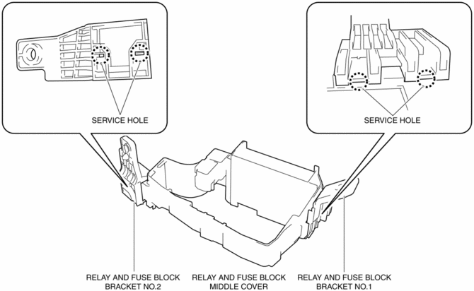
2. While pressing the relay and fuse block middle cover tab in the direction of arrow (1) shown in the figure, pull out the bracket in the direction of arrow (2) to detach the relay and fuse block middle cover tab from the bracket.
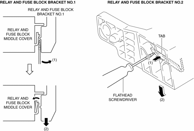
3. Detach all the relay and fuse block middle cover tabs from the bracket and remove the bracket from the relay and fuse block middle cover.
4. Assemble in the reverse order of disassembly.
 Relay And Fuse Block Disassembly/Assembly
1. Insert a tape-wrapped flathead screwdriver into the service hole in the position
shown in the figure.
2. Move the flathead screwdriver in the direction of the arrow (1) shown in the
figur ...
 Relay And Fuse Block Removal/Installation
1. Remove the battery tray..
2. Remove the air cleaner case..
3. While pressing the relay and fuse block upper cover tab in the direction of
the arrow (1) shown in the figure, lift up the relay ...
Other materials:
Electric Power Steering (Eps) Control Module
Purpose/ Function
The EPS control module (CM) calculates the optimum assist current based on
the steering torque signal from the torque sensor installed to the steering
column and the vehicle speed signal sent via CAN transmission from the PCM.
The EPS CM controls the following ...
Control System [Manual Air Conditioner]
Outline
Refrigerant pressure sensor adopted in which refrigerant pressure is changed
into a linear electric signal and precise information is transmitted.
Climate control unit with enlarged operation dials and switches adopted
Structural View
System Wiring Diagram
...
Rear Seat Back Removal/Installation
CAUTION:
When removing or putting in the rear seat, contact with the surrounding areas
of the vehicle could cause scratches and damage. When removing or putting in
the rear seat, always use two or more persons to perform the work and be careful
not to scratch or damage the rear seat ...
