
Mazda CX-5 Service & Repair Manual: Refrigerant Pressure Sensor [Full Auto Air Conditioner]
Purpose
-
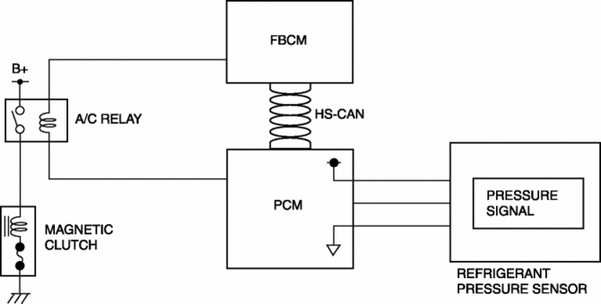
The refrigerant pressure sensor detects the refrigerant pressure in the refrigerant cycle.
Function
-
The refrigerant pressure sensor converts the detected refrigerant pressure to an electric signal and sends it to the PCM.
Construction
-
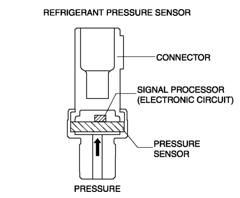
The refrigerant pressure sensor is installed on the cooler pipe.
-
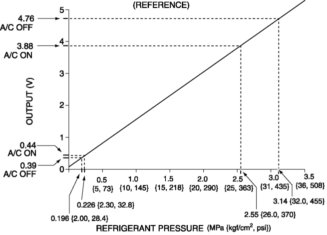
A capacitance type refrigerant pressure sensor, which converts refrigerant pressure into a linear electric signal, has been adopted.
-
Consists of a pressure detecting part and signal processing part.
-
The pressure detecting part is a variable capacity condenser, which changes capacitance according to the pressure.
-
The signal processing part detects the capacitance of pressure detecting part, converts it to voltage, then outputs it to the climate control unit.
Operation
Capacitance type
-
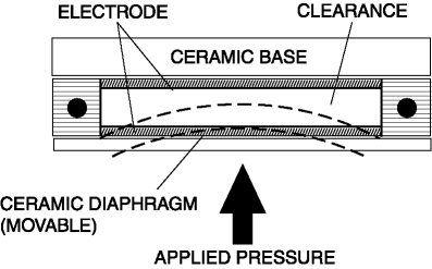
There is a clearance between the movable ceramic diaphragm and the ceramic base, and each side has an electrode.
-
When pressure is applied from the ceramic diaphragm side, the ceramic diaphragm deforms, and the clearance between the electrodes changes. As a result, capacitance is changed and pressure is detected.
Fail-safe
-
Function not equipped.
 Refrigerant Pressure Sensor Removal/Installation [Manual Air Conditioner]
1. Disconnect the negative battery cable..
2. Discharge the refrigerant..
3. Disconnect the refrigerant pressure sensor connector.
CAUTION:
If moisture or foreign material enters the ref ...
 Refrigerant Pressure Sensor [Manual Air Conditioner]
Purpose
The refrigerant pressure sensor detects the refrigerant pressure in the refrigerant
cycle.
Function
The refrigerant pressure sensor converts the detected refrigerant pre ...
Other materials:
Driver Side Air Bag Module [Standard Deployment Control System]
Purpose
When the driver-side air bag module receives an impact from a frontal or
frontal offset collision, the operation (deployment) of the air bag mediates
the impact to the head and face of the driver.
Function
When the driver-side air bag module receives an impact from ...
Decoration Panel Removal/Installation
CAUTION:
Affix protective tape to the position shown in the figure.
1. Disconnect the negative battery cable..
2. Open the glove compartment.
3. Insert a tape-wrapped flathead screwdriver in the position indicated by the
arrow (1) in the figure and detach clip A.
4. ...
Oil Seal (Control Valve Body) Replacement [Fw6 A EL, Fw6 Ax EL]
1. Disconnect the negative battery cable..
2. Remove the air cleaner component..
3. Disconnect the control valve body connector.
CAUTION:
Make sure that your hand does not touch the terminal as the connector terminal
could be damaged.
Water or foreign objects entering th ...
