Mazda CX-5 Service & Repair Manual: Rear Fender Panel Installation [Panel Replacement]
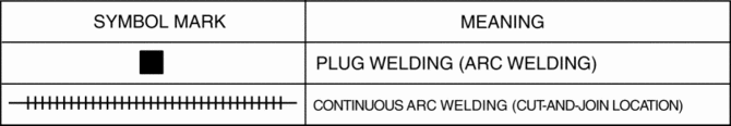
Symbol Mark
Installation Procedure
1. When installing new parts, measure and adjust the body as necessary to conform with standard dimensions.
2. Drill holes for the plug welding before installing the new parts.
3. After temporarily installing new parts, make sure the related parts fit properly.
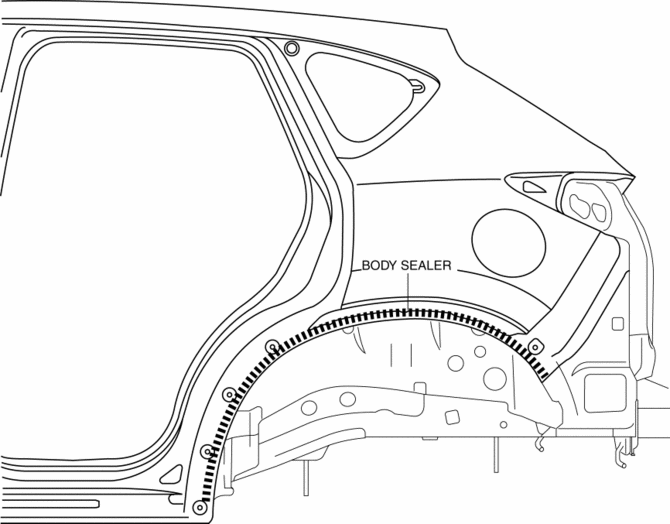
4. Before installing new parts, apply body sealer to the wheel arch line.
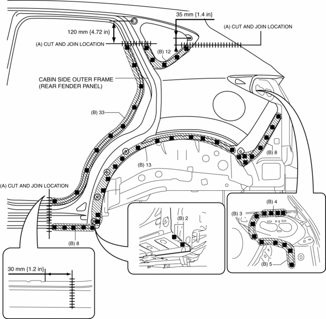
5. Cut and join the 3 locations indicated by (A) shown in the figure.
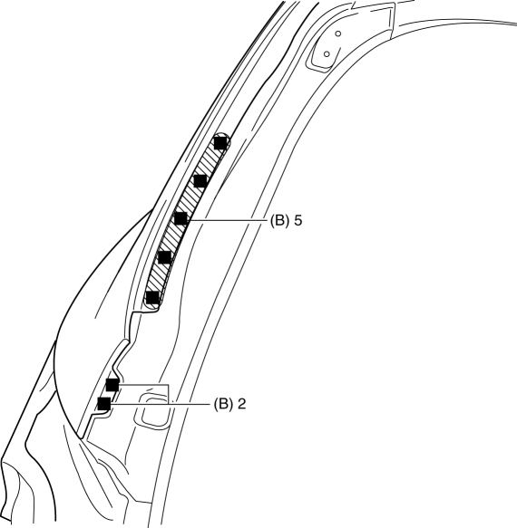
6. Plug weld the 95 locations indicated by (B) shown in the figure, then install the cabin side outer frame (rear fender panel).
 Rear Fender Lower Panel Removal [Panel Replacement]
Symbol Mark
Removal Procedure
1. Drill the 20 locations shown in the figure.
2. Remove the rear fender lower panel. ...
 Rear Fender Panel Removal [Panel Replacement]
Symbol Mark
Removal Procedure
CAUTION:
Avoid cutting with a blowtorch or similar tools as the insulator (shaded
area) is flammable.
1. Rough cut the 3 locations indicated by ...
Other materials:
Auto Leveling Sensor Inspection
1. Disconnect the negative battery cable..
2. Remove the auto leveling sensor..
3. Prepare three dry cell batteries (1.5 V).
4. Connect the three dry cell batteries in a series.
5. Connect the positive pole of the dry cell battery to auto leveling sensor
terminal C, and the negative po ...
Front Bumper Disassembly/Assembly
1. Disassemble in the order indicated in the table.
1
Rivet
2
Grille bracket
3
Front bumper retainer
4
Screw
5
Radiator grille
6
O ...
Liftgate Upper Trim Removal/Installation
1. Take the shaded area shown in the figure, detach tab A while pulling the liftgate
upper trim in the direction of the arrow (1) shown in the figure, then detach clips
B, clip C and pin D while pulling in the direction of the arrow (2).
2. Take the shaded area shown in the figure, detach ...
