Mazda CX-5 Service & Repair Manual: Vanity Mirror Illumination Inspection
1. Disconnect the negative battery cable..
2. Remove the sunvisor..
3. Verify that the continuity between the vanity mirror illumination terminals is as indicated in the table.
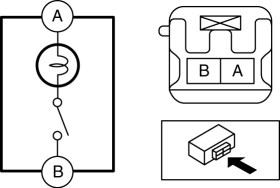
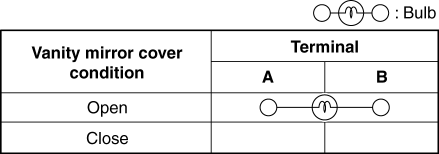
-
If not as indicated in the table, replace the sunvisor.
 Vanity Mirror Illumination Bulb Removal/Installation
1. Disconnect the negative battery cable..
2. Insert a tape-wrapped flathead screwdriver into the service hole in the position
shown in the figure.
3. Move a flathead screwdriver in the dire ...
 Power Outer Mirror Switch Inspection
1. Disconnect the negative battery cable..
2. Remove the power outer mirror switch..
3. Verify that the continuity between the power outer mirror switch terminals
is as indicated in the table.
...
Other materials:
Afs Off Indicator Light
Purpose
The AFS OFF indicator light notifies the user that the AFS is stopped or
a malfunction occurs in the AFS.
Function
The AFS OFF indicator light illuminates when the AFS is stopped and flashes
when a malfunction occurs in the AFS.
Construction
When the mi ...
Splash Shield Removal/Installation
Front
Front splash shield No.1
1. Set the mudguard aside..
2. Remove fasteners A.
3. Remove the front splash shield No.1.
4. Install in the reverse order of removal.
Front splash shield No.2
1. Remove screw B.
2. Remove fasteners C.
3. Remove the front splash shield No.2.
4. ...
Fuel Pump Control
Outline
By switching the fuel pump discharge amount, reduced power consumption and
improved fuel economy have been realized.
The PCM determines the optimum fuel pump drive force according to the engine
operation conditions, and sends the fuel pump drive signal to the fuel pump
...
