
Mazda CX-5 Service & Repair Manual: Expansion Valve Removal/Installation
1. Disconnect the negative battery cable..
2. Discharge the refrigerant from the system..
CAUTION:
-
If moisture or foreign material enters the refrigeration cycle, cooling ability will be lowered and abnormal noise will occur. Always immediately plug all open fittings after removing any refrigeration cycle parts to keep moisture or foreign material out of the cycle.
3. Remove the nut.
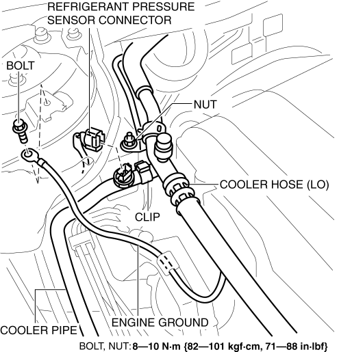
4. Remove the clip.
5. Disconnect the refrigerant pressure sensor connector.
6. Disconnect the engine ground.
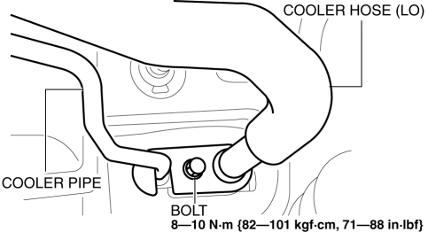
7. Remove the bolt and disconnect the cooler hose (LO) and cooler pipe. Do not allow compressor oil to spill.
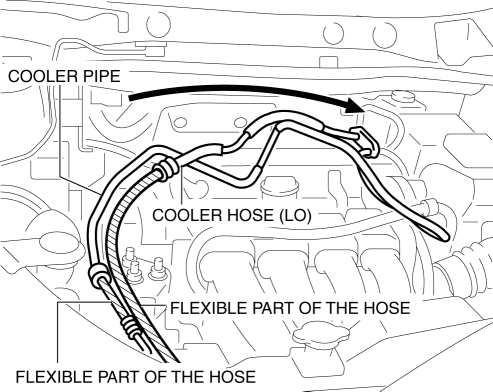
8. Set the cooler hose (LO) and cooler pipe aside as shown in the figure while being careful not to let remaining oil in the pipes to spill.
CAUTION:
-
When setting the cooler hose (LO) and cooler pipe aside, only bend the flexible part of the hose. If force is applied to areas other than the flexible hose, the pipe will bend and could be damaged.
9. Remove the bolt.
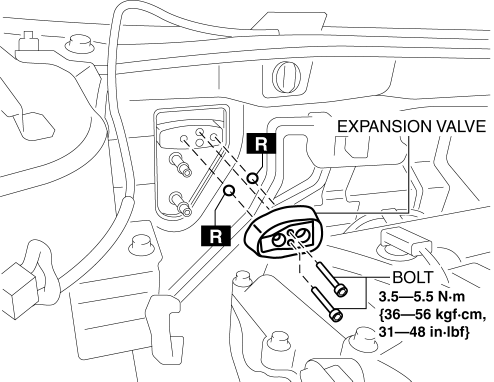
10. Remove the expansion valve. Do not allow compressor oil to spill.
11. Install in the reverse order of removal.
12. Perform the refrigerant system performance test..
 Expansion Valve
Purpose
The expansion valve atomizes liquid refrigerant to facilitate cooling of
the evaporator.
Function
The expansion valve reduces the pressure of liquid refrigerant rapidly ...
 Fan Switch Inspection [Manual Air Conditioner]
1. Disconnect the negative battery cable..
2. Remove the following parts:
a. Shift lever knob (MTX).
b. Glove compartment.
c. Front console box.
d. Shift panel.
e. Upper panel.
f. Rear c ...
Other materials:
Headlight Auto Leveling System Initialization
NOTE:
The AFS control module records the vehicle height while it is unoccupied
by performing the headlight auto leveling system initial setting.
Perform headlight auto leveling system initial setting if any of the following
work is performed.
AFS control module rep ...
Manual Transaxle Oil Replacement [C66 M R]
1. Park the vehicle on level ground.
2. Remove the front under cover No.2..
3. Remove the drain plug and gasket, and drain the manual transaxle oil.
4. Install a new gasket and the drain plug.
Tightening torque
39—59 N·m {4.0—6.0 kgf·m, 29—43 ft·lbf}
5. Remove the ...
Side Wall Removal/Installation
1. Pull the side wall in the direction of the arrow in the order of (1), (2)
and remove it while detaching hooks A and clip B.
2. Pull the side wall in the direction of the arrow (3) and remove it while detaching
the guide C.
CAUTION:
If the hooks A and clip B is removed forceful ...
