
Mazda CX-5 Service & Repair Manual: Rear ABS Wheel Speed Sensor Inspection [Awd]
Installation Visual Inspection
1. Inspect the following items:
-
If there is any malfunction, replace the applicable part.
a. Excessive play of the ABS wheel-speed sensor
b. Deformation of the ABS wheel-speed sensor
c. Deformation or damage of the ABS sensor rotor
Clearance Inspection
1. Remove the ABS wheel-speed sensor.
2. Measure the distance between the ABS wheel-speed sensor installation surface and the ABS sensor rotor. This is dimension A.
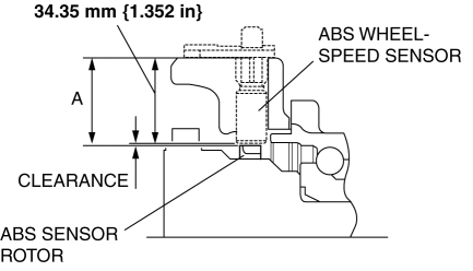
3. Calculate the clearance between the front ABS wheel-speed sensor and the ABS sensor rotor using the following formula:
-
Clearance (mm {in}) = A-34.35 {1.352}
4. Verify that the clearance between the ABS sensor rotor and the ABS wheel-speed sensor is as indicated below.
-
If there is any malfunction, replace it.
-
Clearance
-
0.3—1.4 mm {0.02—0.05 in}
Sensor Output Value Inspection
1. Switch the ignition to off.
2. Connect the M-MDS to the DLC-2.
3. Select the following PIDs using the M-MDS:
-
WSPD_SEN_LR (LR ABS wheel-speed sensor)
-
WSPD_SEN_RR (RR ABS wheel-speed sensor)
4. Start the engine and drive the vehicle.
5. Verify that the display of the M-MDS shows the same value as the speedometer.
-
If there is any malfunction, replace the ABS wheel-speed sensor.
 Planetary Gear [Fw6 A EL, Fw6 Ax EL]
Purpose/Function
The planetary gear is a mechanism which shifts the drive force from the engine.
The planetary gear consists of multiple gears which rotate individually while
revolving. B ...
 Rear Crossmember Removal/Installation [Awd]
WARNING:
Verify that the crossmember is securely supported by a jack. If the rear
crossmember falls off, it can cause serious injury or death, and damage to the
vehicle.
CAUTION:
...
Other materials:
Forced Ignition On
NOTE:
In order to perform a forced ignition ON, the M-MDS is necessary. If the
servicing is being done outside of an Authorized Mazda dealership, contact an
Authorized Mazda dealership for instructions.
The forced ignition ON procedure forces a power supply to each part when
...
Air Bag System Warning Light [Standard Deployment Control System]
Purpose
The air bag system warning light notifies the driver of a malfunction in
the SRS air bag system.
Function
If a malfunction occurs in the SRS air bag system, the air bag system warning
light illuminates or flashes.
Construction
LEDs (light-emitting d ...
PID/Data Monitor Inspection [Standard Deployment Control System]
1. Connect the M-MDS to the DLC?2.
2. After the vehicle is identified, select the following items from the initialization
screen of the M-MDS.
a. Select “DataLogger”.
b. Select “Modules”.
c. Select “RCM”.
3. Select the applicable PID from the PID table.
4. Verify the PID da ...
