Mazda CX-5 Service & Repair Manual: Pre Tensioner Seat Belt [Standard Deployment Control System]
Purpose
-
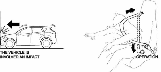
The pre-tensioner seat belt retracts and tightens the seat belt webbing to protect the front passengers during a collision.
Function
-
The pre-tensioner seat belts operate (deploy) based on the operation signal from the SAS control module to instantly retract and tighten the belt webbing, restraining the driver and front passenger.

Construction
-
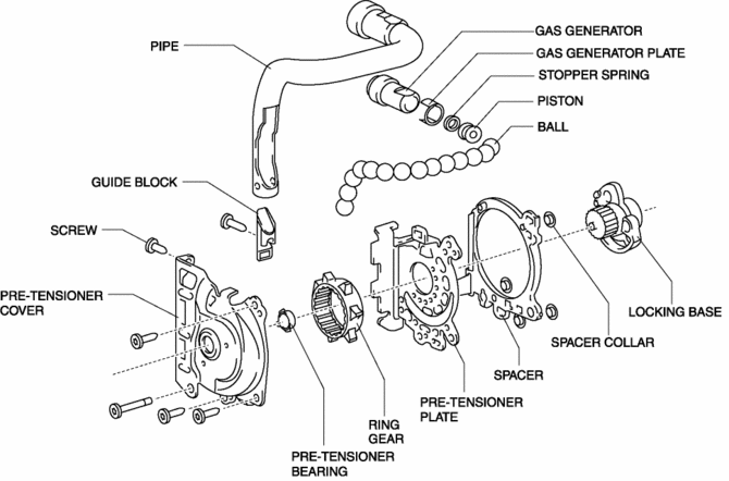
The pre-tensioner seat belt is installed to the front seat belt retractor.
-
The pre-tensioner seat belt consists of the following parts shown in the figure:

Operation
Normal operation (pre-tensioner non-operation)
-
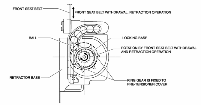
Normally, there is a gap between the locking base and the ring gear.
-
The ring gear rotates in conjunction with the withdrawal and retraction of the front seat belts, however, in the pre-tensioner part it is kept separated.

Pre-tensioner activation
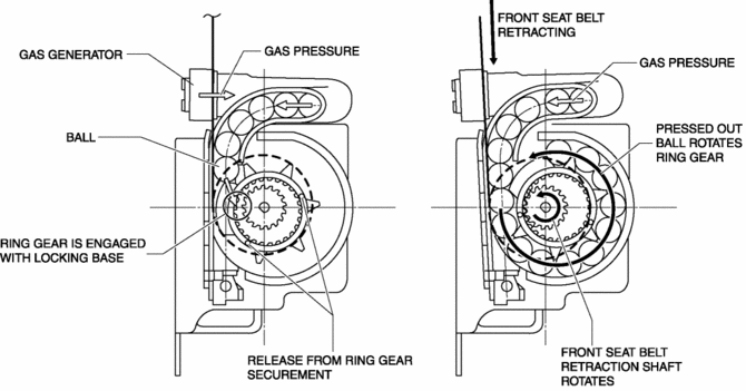
1. The gas generator produces gas when it receives an operation signal from the SAS control module.
2. The ball in the cylinder is pressed by the gas pressure and the ring gear is removed from its securement.
3. The ring gear is engaged with the locking base and the force of the ball being pressed out is transmitted to the retraction shaft.
4. The front seat belt is retracted in conjunction with the rotation of the retraction shaft.

Fail-safe
-
Function not equipped.
 Passenger Side Air Bag Module [Two Step Deployment Control System]
Purpose
When the passenger-side air bag module receives an impact from a frontal
or frontal offset collision, the operation (deployment) of the air bag mediates
the impact to the head and ...
 Pre Tensioner Seat Belt [Two Step Deployment Control System]
Purpose
The pre-tensioner seat belt retracts and tightens the seat belt webbing to
protect the front passengers during a collision.
Function
The pre-tensioner seat belts operate ...
Other materials:
Rear Body Control Module (Rbcm)
Outline
Positioned at the rear of the vehicle, the rear body control module (RBCM)
performs numerous system controls for functions at the vehicle rear.
Function
The rear body control module (RBCM) controls the system based on the input/output
signals.
The functions ...
Sirius Satellite Radio Unit Removal/Installation
CAUTION:
The audio unit communicates with the SIRIUS satellite radio unit and records
the presence/non-presence of the SIRIUS satellite radio unit when the ignition
is switched to ACC or ON (engine off or on) after connecting the negative battery
cable.
If the commander ...
A/C Unit Disassembly/Assembly
1. Disassemble in the order indicated in the table.
CAUTION:
If a non-specified grease is used, it may result in abnormal noise or improper
operation of the links. Apply only the specified grease to each link.
2. Assemble in the reverse order of disassembly.
...
