Mazda CX-5 Service & Repair Manual: Passenger Side Air Bag Module [Two Step Deployment Control System]
Purpose
-
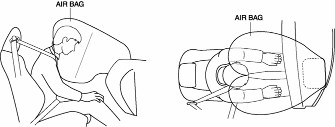
When the passenger-side air bag module receives an impact from a frontal or frontal offset collision, the operation (deployment) of the air bag mediates the impact to the head and face of the front passenger.
Function
-
When the passenger-side air bag module receives an impact from a frontal or frontal offset collision, the air bag is operated (deployed) by the operation signal sent from the SAS control module.
-
A twin-bag type air bag has been adopted for the passenger-side air bag module.
-
The twin bags protect occupants by the following operations:
-
The head goes between the bags to softly restrain the face as a result of the low reaction force.
-
Occupant shoulders are supported by the projection of the bag to restrain the upper body of the occupant.
Construction
-
The passenger-side air bag module is installed to the instrument panel.
Operation
-
The passenger-side air bag module operates (deploys) the air bag by activating the internal inflator.
-
The inflator operates (deploys) in the following order:
Inflator No.1
1. When the driver-side air bag module receives an operation (deployment) signal from the SAS control module, the igniter built into inflator No.1 builds up heat and ignites the inflammation agent.
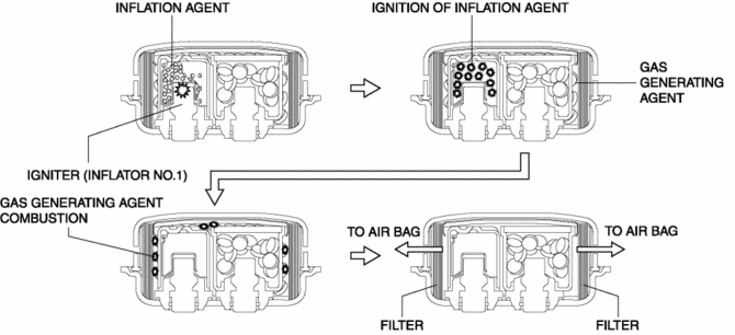
2. The ignition of the inflammation agent causes the combustion of a gas-generating agent which releases nitrogen gas.
3. The nitrogen gas is cooled at the filter and the filtrate is injected into the air bag.
Inflator No.2
1. When the driver-side air bag module receives an operation (deployment) signal from the SAS control module, the igniter built into inflator No.2 builds up heat and ignites the inflammation agent.
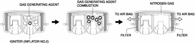
2. The ignition of the inflammation agent causes the combustion of a gas-generating agent which releases nitrogen gas.
3. The nitrogen gas is cooled at the filter and the filtrate is injected into the air bag.
Fail-safe
-
Function not equipped.
 Passenger Side Air Bag Module [Standard Deployment Control System]
Purpose
When the passenger-side air bag module receives an impact from a frontal
or frontal offset collision, the operation (deployment) of the air bag mediates
the impact to the head and ...
 Pre Tensioner Seat Belt [Standard Deployment Control System]
Purpose
The pre-tensioner seat belt retracts and tightens the seat belt webbing to
protect the front passengers during a collision.
Function
The pre-tensioner seat belts operate ...
Other materials:
Power Window Main Switch
Purpose
Remote control of door glass open/close and power outer mirror adjustment
are possible with occupant seated in the cabin.
Function
Power window main switch
Manual
When the power window main switch is operated for manual open/close operation,
it sends ...
Wheel Balance Adjustment (Aluminum Alloy Wheel)
CAUTION:
Adjust the outer wheel balance first, then the inner wheel balance.
Be careful not to scratch the wheels.
Adhesive-type Balance Weight (Outer)
1. Remove the old balance weight from the wheel.
2. Remove the double-sided adhesive tape remaining on the wheel, then ...
Steering Wheel
Steering Wheel
WARNING
Never adjust the steering wheel while the vehicle is moving: Adjusting the steering
wheel while the vehicle is moving is dangerous.
Moving it can very easily cause the driver to abruptly turn to the left or right.
This can lead to loss of control or an accident.
Steeri ...
