Mazda CX-5 Service & Repair Manual: DRL (Daytime Running Light) System
Outline
-
The DRL system automatically switches the headlights to HI beams (50% dim) or illuminates the DRL bulb when the ignition is switched ON (engine on), the parking brake is released, and the shift lever is in a position other than P (ATX).
-
The front body control module (FBCM) performs DRL system fail-safe..
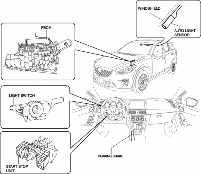
Structural View
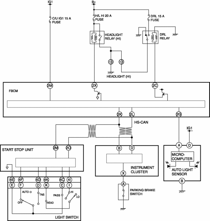
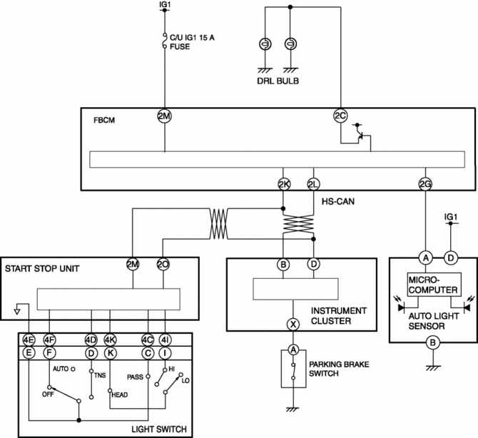
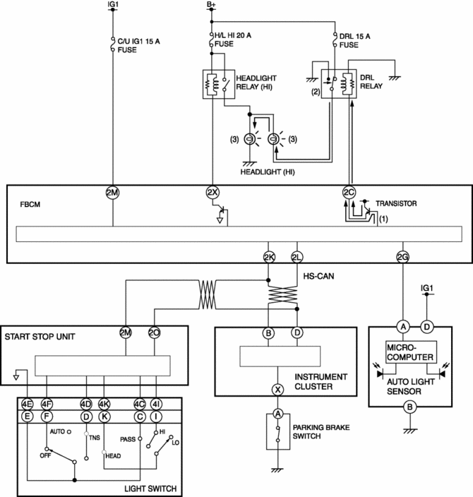
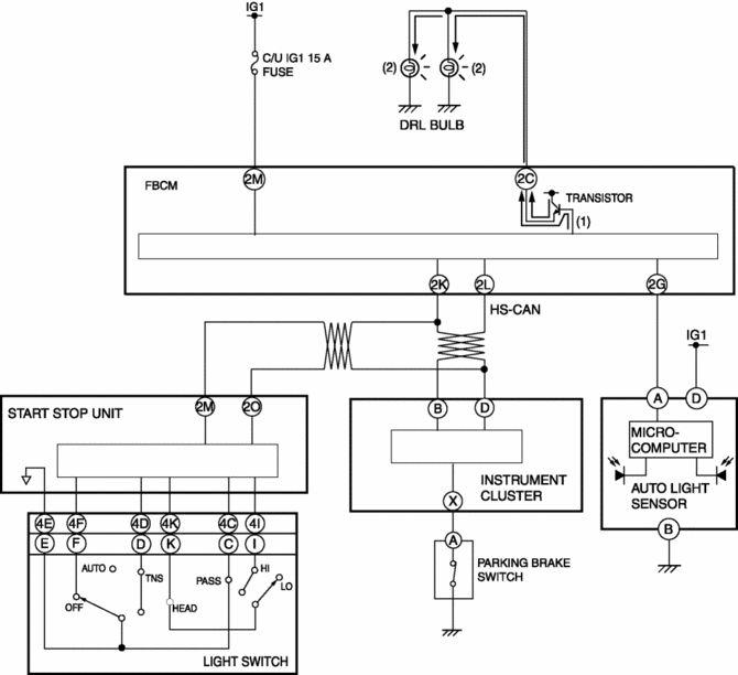
System Wiring Diagram
Halogen type
Discharge type
Operation (Halogen type)
Operation condition
—: Not applicable|
Engine switch |
Shift lever position (ATX) |
Parking brake switch |
Light switch |
Dimmer switch |
Flash-to-pass switch |
Headlight (LO) |
Headlight (HI) |
DRL mode |
|
ON |
Other than P position |
OFF (Parking brake lever released) |
OFF/TNS/AUTO*1 |
LO |
OFF |
OFF |
ON (DRL) |
ON |
|
ON |
— |
— |
— |
|||||
|
HI |
OFF |
OFF |
ON (DRL) |
ON |
||||
|
ON |
ON |
ON |
OFF |
|||||
|
HEAD |
LO |
OFF |
ON |
OFF |
OFF |
|||
|
ON |
— |
— |
— |
|||||
|
HI |
OFF |
ON |
ON |
OFF |
||||
|
ON |
ON |
ON |
OFF |
|||||
|
ON (Parking brake lever pulled) |
OFF/TNS |
LO |
OFF |
OFF |
OFF |
OFF |
||
|
ON |
— |
— |
— |
|||||
|
HI |
OFF |
OFF |
OFF |
OFF |
||||
|
ON |
ON |
ON |
OFF |
|||||
|
HEAD |
LO |
OFF |
ON |
OFF |
OFF |
|||
|
ON |
— |
— |
— |
|||||
|
HI |
OFF |
ON |
ON |
OFF |
||||
|
ON |
ON |
ON |
OFF |
|||||
|
OFF |
— |
— |
OFF/TNS |
LO |
OFF |
OFF |
OFF |
OFF |
|
ON |
— |
— |
— |
|||||
|
HI |
OFF |
OFF |
OFF |
OFF |
||||
|
ON |
ON |
ON |
OFF |
|||||
|
HEAD |
LO |
OFF |
ON |
OFF |
OFF |
|||
|
ON |
— |
— |
— |
|||||
|
HI |
OFF |
ON |
ON |
OFF |
||||
|
ON |
ON |
ON |
OFF |
*1 If the auto light sensor detects that the TNS and headlights are off when the light switch is in the AUTO position, the DRL illuminates.
1. If the DRL mode operation conditions are met, the front body control module (FBCM) turns on the DRL circuit transistor.
2. When the transistor turns on, the DRL relay turns on.
3. If the DRL relay turns on, the electrical current flows in-line relative to the left/right headlight (HI) circuits and the headlights (HI) turn on at half the brightness of normal illumination.
Operation (Discharge type)
Operation condition
—: Not applicable|
Engine switch |
Shift lever position (ATX) |
Parking brake switch |
Light switch |
Dimmer switch |
Flash-to-pass switch |
Headlight (LO) |
Headlight (HI) |
DRL |
DRL mode |
|
ON |
Other than P position |
OFF (Parking brake lever released) |
OFF/TNS/AUTO*1 |
LO |
OFF |
OFF |
OFF |
ON |
ON |
|
ON |
— |
— |
— |
— |
|||||
|
HI |
OFF |
OFF |
OFF |
ON |
ON |
||||
|
ON |
ON |
ON |
OFF |
OFF |
|||||
|
HEAD |
LO |
OFF |
ON |
OFF |
OFF |
OFF |
|||
|
ON |
— |
— |
— |
— |
|||||
|
HI |
OFF |
ON |
ON |
OFF |
OFF |
||||
|
ON |
ON |
ON |
OFF |
OFF |
|||||
|
ON (Parking brake lever pulled) |
OFF/TNS |
LO |
OFF |
OFF |
OFF |
OFF |
OFF |
||
|
ON |
— |
— |
— |
— |
|||||
|
HI |
OFF |
OFF |
OFF |
OFF |
OFF |
||||
|
ON |
ON |
ON |
OFF |
OFF |
|||||
|
HEAD |
LO |
OFF |
ON |
OFF |
OFF |
OFF |
|||
|
ON |
— |
— |
— |
— |
|||||
|
HI |
OFF |
ON |
ON |
OFF |
OFF |
||||
|
ON |
ON |
ON |
OFF |
OFF |
|||||
|
OFF |
— |
— |
OFF/TNS |
LO |
OFF |
OFF |
OFF |
OFF |
OFF |
|
ON |
— |
— |
— |
— |
|||||
|
HI |
OFF |
OFF |
OFF |
OFF |
OFF |
||||
|
ON |
ON |
ON |
OFF |
OFF |
|||||
|
HEAD |
LO |
OFF |
ON |
OFF |
OFF |
OFF |
|||
|
ON |
— |
— |
— |
— |
|||||
|
HI |
OFF |
ON |
ON |
OFF |
OFF |
||||
|
ON |
ON |
ON |
OFF |
OFF |
*1 If the auto light sensor detects that the TNS and headlights are off when the light switch is in the AUTO position, the DRL illuminates.
1. If the DRL mode operation conditions are met, the front body control module (FBCM) turns on the DRL circuit transistor.
2. When the transistor turns on, the DRL bulbs are illuminated.
 DRL (Daytime Running Light) Bulb Removal/Installation
1. Disconnect the negative battery cable..
2. Disconnect the connector.
3. Rotate the DRL bulb in the direction of the arrow (1) shown in the figure
and remove it from the front combination ...
 Discharge Headlight Bulb
Purpose, Function
Charges the internal metallic element and emits white light resembling sunlight.
Construction
A mercury-free bulb has been adopted for the discharge headlight bul ...
Other materials:
Meters and Gauges
1 Speedometer
2 Odometer, Trip Meter and Trip Meter Selector
3 Tachometer
4 Fuel Gauge
5 Dashboard Illumination
6 Outside Temperature Display
7 Trip Computer and INFO Switch
Speedometer
The speedometer indicates the speed of the vehicle.
Odometer, Trip Meter and Trip Meter Selector
...
Starter Interlock Switch Removal/Installation [C66 M R]
1. Disconnect the negative battery cable..
2. Disconnect the starter interlock switch connector.
3. Remove the starter interlock using the following procedure:
a. Detach hook A in the direction of the arrow shown in the figure.
b. Slide the starter interlock switch in the direction of th ...
Start Stop Unit
Purpose
Performs control of several systems based on input/output signals from switches.
Function
The start stop unit controls systems based on the input/output signals.
The functions which are controlled are as follows:
Control Table
Control ...
